Most industrial motors operate on voltages that range from 240 to 480 volts. Magnetic control systems, however, generally operate on 120 volts. A control transformer is used to step the 240 or 480 volts down to 120 volts to operate the control system. There is really nothing special about a control transformer except that most of them are made with two primary windings and one secondary winding. Each primary winding is rated at 240 volts and the secondary winding is rated at 120 volts. This means there is a turns ratio of 2:1 (2 to 1) between each primary winding and the secondary winding. For example, assume that each primary winding contains 200 turns of wire and the secondary winding contains 100 turns. There are two turns of wire in each primary winding for every one turn of wire in the secondary.
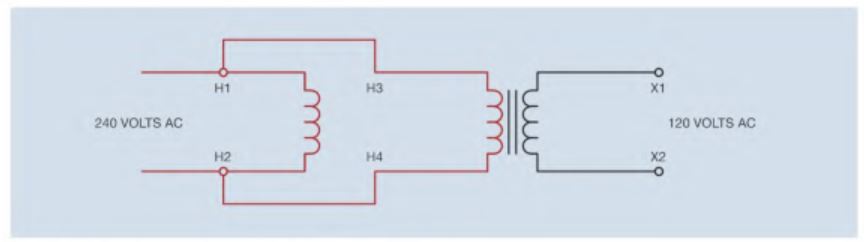
One of the primary windings of the control transformer is labeled HI and H2. The other primary winding is labeled H3 and H4. The secondary winding is labeled XI and X2. If the transformer is to be used to step 240 volts down to 120 volts. Notice that in Figure 6-1 the HI and H3 leads are connected together, and the H2 and H4 leads are connected together. Because the voltage applied to each primary winding is same, the effect is the same as having only one primary winding with 200 turns of wire in it. This means that when the transformer is connected in this manner, the turns ratio is 2:1. When 240 volts are connected to the primary winding, the
secondary voltage is 120 volts.
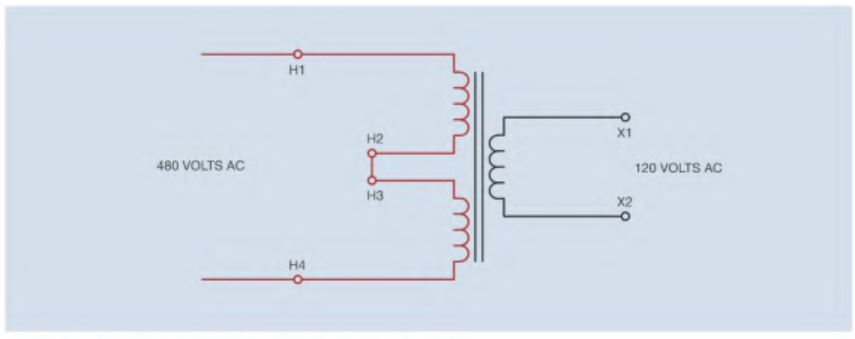
If the transformer is to be used to step 480 volts down to 120 volts, the primary windings are connected in series. With the windings connected in series, the primary winding now has a total of 400 turns of wire, which makes a turns ratio of 4:1. When 480 volts arc connected to the primary winding, the secondary winding has an output of 120 volts.
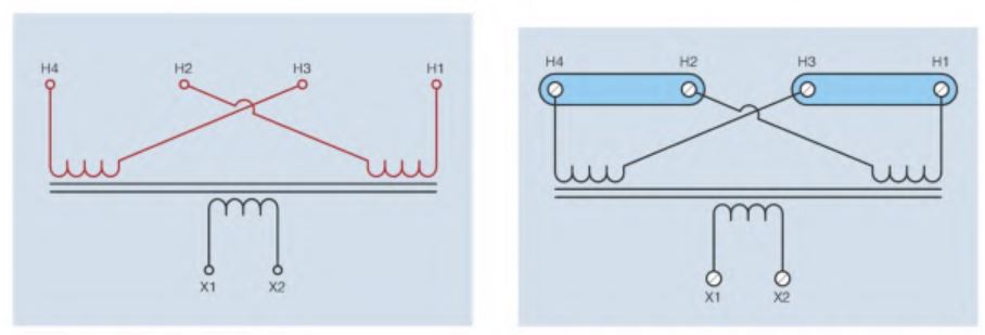
Control transformers generally have screw terminals connected to the primary and secondary leads. The H2 and H3 leads are crossed to make connection of the primary winding easier. For example, if the transformer is to be connected for 240-voll operation. This connection can be made on the transformer by using one metal link to connect leads HI and H3, and another metal link to connect H2 and H4. If the transformer is to be used for 480-volt operation.
Multi-Tapped Control Transformers
Some control transformers provide connection to different voltages by providing different taps on the high voltage winding. The transformer in this example can be connected to 208, 277, or 380 volts. The secondary or low voltage winding provides an output of 120 volts.
If the transformer is connected to 208 volts, primary taps HI and H2 would be used. Taps H3 and H4 are left disconnected. If the transformer is to be connected to 277 volts, taps HI and H3 would be used. Taps H2 and H4 would be left disconnected. Taps HI and H4 can be connected to 380 volts, which is a common voltage used in Europe.
Grounded and Floating Control Systems
One side of the secondary winding of a control transformer is often grounded. When this is done, the control system is referred to as a grounded system. Many industries prefer to ground the control system and it is a very common practice. Some technicians believe that it is an aid when troubleshooting a problem. Grounding one side of the control transformer permits one lead of a voltmeter to be connected to any grounded point and the other voltmeter lead is used to test voltage at various locations throughout the circuit.
It is also a common practice to not ground one side of the control transformer. This is generally referred to as a floating system. If one voltmeter probe was connected to a grounded point, the meter reading would be erroneous or meaningless because there is not a complete circuit. High impedance voltmeters would probably indicate some amount of voltage caused by the capacitance of the ground and induced voltage produced by surrounding magnetic fields. These are generally referred to as ghost voltages. A low impedance meter such as a plunger type voltage tester would indicate no voltage. Accurate voltage measurement can be made in a float control system, however, by connecting one voltmeter probe directly to one side of the control transformer.
Transformer Fusing
Control transformers are generally protected by fuses or circuit breakers. Protection can be placed on the primary or secondary side of the transformer, and some industries prefer protection in both sides. NEC Section 430.72(C) lists requirements for the protection of transformers employed in motor control circuits. This section basically states that control transformers that have a primary current of less than 2 amperes shall be protected by an overcurrent device set at not more than 500 percent of the rated primary current. This large percentage is necessary because of the high in-rush current associated with transformers. To determine the rated current of the transformer, divide the volt-ampere rating of the transformer by the primary voltage.
The secondary fuse size can be set at a lower percentage of the rated current because the secondary does not experience the high in-rush current of the primary. Because primary and secondary fuse protection is common throughout industry