Transformer Operation
A transformer is used to transfer AC energy from one circuit to another. The two circuits are coupled by a magnetic field that is linked to both instead of a conductive electrical path. This transfer of energy may involve an increase or decrease in voltage, but the frequency will be the same in both circuits. In addition, a transformer doesn’t change power levels between circuits. If you put 100 VA into a transformer, 100 VA (minus a small amount of losses) comes out. The average efficiency of a transformer is well over 90 percent, in part because a transformer has no moving parts. A transformer can be operated only with AC voltage because no voltage is induced if there is no change in the magnetic field. Trying to operate a transformer from a constant DC voltage source will cause a large amount of DC current to flow, which can destroy the transformer.
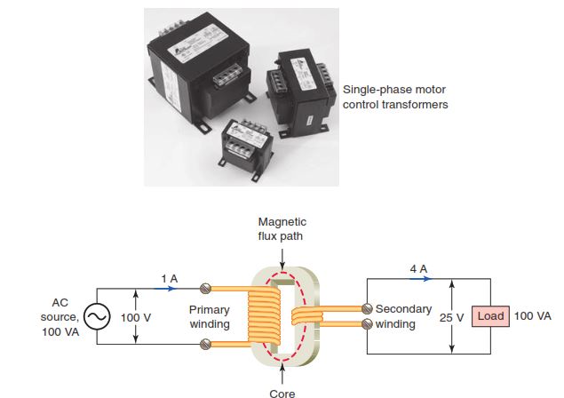
Figure 3-18 illustrates a simplified version of a single-phase (1ϕ) transformer. The transformer consists of two electrical conductors, called the primary winding and the secondary winding. The primary winding is fed from a varying alternating current, which creates a varying magnetic field around it. According to the principle of mutual inductance, the secondary winding, which is in this varying magnetic field, will have a voltage induced into it. In its most basic form, a transformer is made up of the:
- Core, which provides a path for the magnetic lines of force.
- Primary winding, which receives energy from the source.
- Secondary winding, which receives energy from the primary winding and delivers it to the load.
- Enclosure, which protects the components from dirt, moisture, and mechanical damage.
The essentials that govern the operation of a transformer are summarized as follows:
- If the primary has more turns than the secondary, you have a step-down transformer that reduces the voltage.
- If the primary has fewer turns than the secondary, you have a step-up transformer that increases the voltage.
- If the primary has the same number of turns as the secondary, the outgoing secondary voltage will be the same as the incoming primary voltage. This is the case for an isolation transformer.
- In certain cases, one large coil of wire can serve as both the primary and secondary. This is the case with autotransformers.
- The primary volt-amperes (VA) or kilovolt-amperes (kVA) of a transformer will be equal to that of the secondary less a small amount of losses.
Transformer Voltage, Current, and Turns Ratio
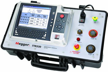
The ratio of turns in a transformer’s primary winding to those in its secondary winding is known as the turns ratio and is the same as the transformer’s voltage ratio. For example, if a transformer has a 10:1 turns ratio, then for every 10 turns on the primary winding there will be 1 turn on the secondary winding. Inputting 10 V to the primary winding steps down the voltage and will produce a 1 V output at the secondary winding. The exact opposite is true for a transformer with a 1:10 turns ratio. A transformer with a 1:10 turns ratio would have 1 turn on the primary winding for every 10 turns on the secondary winding. In this case, inputting 10 V to the primary winding steps up the voltage and will produce 100 volts at the secondary winding. The actual number of turns is not important, just the turns ratio. A transformer turns ratio test set, such as that shown in Figure 3-19, can directly measure the turns ratio of single-phase transformers as well as three-phase transformers. Any deviations from rated values will indicate problems in transformer windings and in the magnetic core circuits.
The voltage ratio of an ideal transformer (one with no losses) is directly related to the turns ratio, while the cur-rent ratio is inversely related to the turns ratio:
Turns secondary / Turns secondary = Voltage primary / Voltage secondary
= Current secondary / Current primary
The following table shows examples of some common single-phase transformer turns ratios based on primary and secondary voltage rating
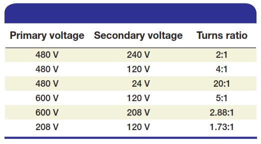
Figure 3-20 shows the schematic diagram of a step-up transformer wound with 900 turns on the primary winding and 1800 turns on the secondary winding. As a step-up unit, this transformer converts low-voltage, high-current power into high-voltage, low-current power. The transformer equations that apply to this circuit are as follows:
Turns ratio = Number of Turns on the primary / Number of Turns on the secondary = 900/1800 = 1:2
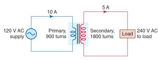
If the voltage of one winding and the turns ratio are known, the voltage of the other winding can be determined.
Primary voltage = Secondary voltage × Turns ratio = 240 V × (1/2) = 120 V
Secondary voltage = Primary voltage / Turns ratio = 120 / (1/2) = 240V
If the current of one winding and the turns ratio are known, the current of the other winding can be determined.
Primary current = Secondary current / Turns ratio = 5A / (1/2) = 10A
Secondary current = Primary current × Turns ratio = 10A x (1/2) = 5A
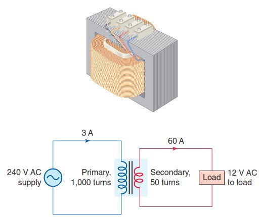
Figure 3-21 shows the schematic diagram of a step-down transformer wound with 1,000 turns on the primary winding and 50 turns on the secondary winding. As a step-down unit, this transformer converts high-voltage, low-current power into low-voltage, high-current power. A larger-diameter wire is used in the secondary winding to handle the increase in current. The primary winding, which doesn’t have to conduct as much current, may be made of a smaller-diameter wire. The transformer equations that apply to this circuit are the same as those for a step-up transformer:
Turns ratio = Number of turns on the primary / Number of turns on the secondary = 1000/50 = 20:1
If the voltage of one winding and the turns ratio are known, the voltage of the other winding can be determined.
Primary voltage = Secondary voltage × Turns ratio = 12V x 20 = 240V
Secondary voltage = Primary voltage / Turns ratio = 240V / 20 = 12V
If the current of one winding and the turns ratio are known, the current of the other winding can be determined.
Primary current = Secondary current / Turns ratio = 60A/20 = 3A
Secondary current = Primary current × Turns ratio = 3 A × 20 = 60A
A transformer automatically adjusts its input current to meet the requirements of its output or load current. If no load is connected to the secondary winding, only a small amount of current, known as the magnetizing current (also known as exciting current), flows through the primary winding. Typically, the transformer is designed in such a way that the power consumed by the magnetizing current is only enough to overcome the losses in the iron core and in the resistance of the wire with which the primary is wound. If the secondary circuit of the transformer becomes overloaded or shorted, primary current increases dramatically also. It is for this reason that a fuse is placed in series with the primary winding to protect both the primary and secondary circuits from excessive current. The most critical parameter of a transformer is its insulation qualities. Failure of a transformer, in most instances, can be traced to a breakdown of the insulation of one or more of the windings.
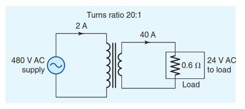
For a purely resistive load, according to Ohm’s law, the amount of secondary winding current equals the sec-ondary voltage divided by the value of the load resistance connected to the secondary circuit (a negligible coil winding resistance is assumed). Figure 3-22 shows the schematic diagram of a step-down transformer with a 20:1 turns ratio connected to a 0.6-Ω resistive load. The transformer equations that apply to this circuit are as follows:
Secondary winding current = Secondary voltage / Load resistance = 24V / 0.6Ω = 40A
Primary winding current = Secondary winding current / Turns ratio = 40A/20 = 2A
Transformer Power Rating
Just as horsepower ratings designate the power capacity of an electric motor, a transformer’s kVA rating indicates its maximum power output capacity. Transformers’ kVA ratings are calculated as follows:
Single-phase loads: kVA = (I × E)/1000
Three-phase loads: kVA = (I × E × 1.732)/1000
The maximum power rating of a transformer can be found on the transformer’s nameplate. Transformers are rated in volt-amperes (VA) or kilovolt-amperes (kVA). You may recall that volt-amperes is the total power supplied to the circuit from the source, and includes real (watts) and reactive (VAR) power. The primary and secondary full-load currents usually are not given. If the volt-ampere rating is given along with the primary voltage, then the primary full-load current can be determined using the following equations:
Single-phase: Full-load current = VA/Voltage hoặc (kVA × 1,000)/Voltage
Three-phase: Full-load current = (kVA × 1,000)/(1.73 × Voltage)
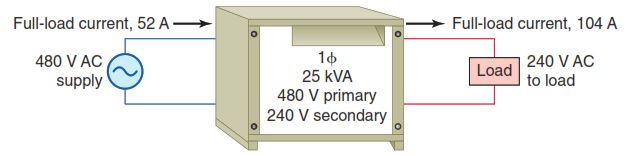
Figure 3-23 shows the diagram for a single-phase 25 kVA transformer, rated 480 V primary and 240 V secondary. The rated full-load primary and secondary cur-rents are calculated as follows:
Primary full-load current = (kVA × 1,000)/Voltage = (25 kVA × 1,000)/480V = 52A
Secondary full-load current = (kVA × 1,000)/Voltage = (25 kVA × 1,000)/240V = 104A
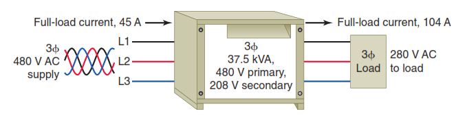
Figure 3-24 shows the diagram for a three-phase 37.5 kVA transformer, rated 480 volts primary and 208 V secondary. The rated full-load primary and secondary currents are calculated as follows:
Primary full-load current = (kVA × 1,000)/(1.73 × Voltage) = (37.5 kVA × 1,000)/(1.73 × 480 V) = 45A
Secondary full-load current = (kVA × 1,000)/(1.73 × Voltage) = (37.5 kVA × 1,000)/(1.73 × 208 V) = 104A
Transformer Performance
The effi ciency of a transformer is a measure of the proportion of the applied energy that is transferred to the load. A transformer does not require any moving parts to transfer energy, and for this reason, power losses associated with them are generally relatively small. Transformer losses in the form waste heat are a combination of core losses and coil losses.
- Core losses (also known as iron or hysteresis losses) consist of those generated by energizing the laminated steel core. Whenever a transformer is energized, the core losses remain essentially constant regardless of how much electric power is flowing through it.
- Coil losses (also known as copper or I 2R losses) result from resistance of the windings and vary with the square of the electric current flowing through the windings.
- At low loads, core losses account for the majority of losses. As the load increases, winding losses repre-sent the greatest loss.
- To reduce core losses, high-efficiency transformers are designed with a better grade of core steel with thinner core laminations than standard-efficiency types.
- Coil losses can be reduced through improved conductor design and increases in the size of the copper conductor used.
- An ideal transformer would have no energy losses, and would be 100 percent efficient. Real transformers, when operated at full load, have an efficiency in the 94 to 98 percent range.
Transformer temperature rise is defined as the average temperature rise of the windings above the ambient (surrounding) temperature when the transformer is loaded at its nameplate rating. Transformers rated for a lower temperature rise:
- Generate less heat.
- Operate more efficiently.
- Last longer than transformers with a higher tem-perature rise rating.
The output secondary voltage of a transformer varies some from no-load to the full-load condition, even with a constant input voltage applied to the primary. This is due in part to:
- Primary and secondary winding resistance and inductance.
- The degree of mutual inductance (magnetic coupling) between the primary and secondary windings.
The measure of how well a power transformer maintains constant secondary voltage over a range of load currents is called the transformer’s voltage regulation and is calculated as follows:
Voltage regulation percentage = (Vno-load − Vfull-load)x100/Vfull-load
where:
- No-load means no load connected to the secondary.
- Full-load means the point at which the transformer is operating at maximum rated secondary current.
The steady-state magnetizing current for a transformer is very low, but the momentary, primary inrush current when it is first energized can be quite high. This may result during the first few cycles of the AC voltage. The magnitude of the inrush current depends on the point on the AC wave where the transformer is switched on. Inrush currents can be typically many times the normal full-load current and result in nuisance tripping of the input over current protection device. A general approach to the problem of dealing with transformer inrush currents is to choose an input over current protection device with the right time delay characteristic to avoid nuisance tripping.