Transformer Polarity
Transformer polarity refers to the relative direction or polarity of the induced voltage between the high-voltage and low-voltage terminals of a transformer. An understanding of transformer polarity markings is essential in making three-phase and single-phase transformer connections. Knowledge of polarity is also required to connect potential and current transformers to power metering and protective relays.
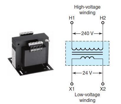
On power transformers, the high-voltage winding leads are marked H1 and H2 and the low-voltage winding leads are marked X1 and X2 (Figure 3-25). By convention, H1 and X1 have the same polarity, which means that when H1 is instantaneously positive, X1 also is instantaneously positive. These markings are used in establishing the proper terminal connections when single-phase transformers are connected in parallel, series, and three-phase configurations.
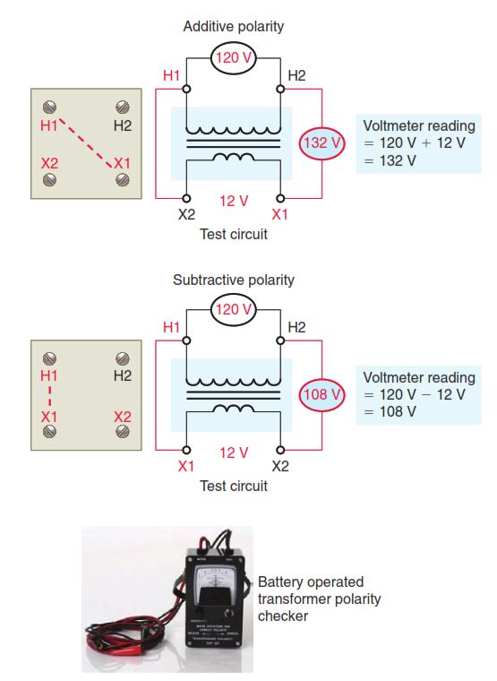
In practice, the four terminals on a single-phase trans-former are mounted in a standard way so the transformer has either additive or subtractive polarity. Whether the polarity is additive or subtractive depends on the location of the H and X terminals. A transformer is said to have additive polarity when terminal H1 is diagonally opposite terminal X1. Similarly, a transformer has subtractive polarity when terminal H1 is adjacent to terminal X1. Figure 3-26 illustrates additive and subtractive transformer terminal markings along with a test circuit that can be used to verify markings. Also shown is a battery-operated transformer polarity checker that can perform the same test.
Single-Phase Transformers
Motor control transformers are designed to reduce supply voltages to motor control circuits. Most AC commercial and industrial motors are operated from three-phase AC supply systems in the 208V to 600V range. However, the control systems for these motors generally operate at 120 V. The major disadvantage to higher-voltage control schemes is that these higher voltages can be much more lethal than 120 V. Additionally, on a higher-voltage control system tied directly to the supply lines, when a short circuit occurs in the control circuit a line fuse will blow or a circuit breaker will trip, but may not do so right away. In some cases, light-duty contacts, such as those in stop buttons or relay contacts, can weld together before the protective device trips or blows.
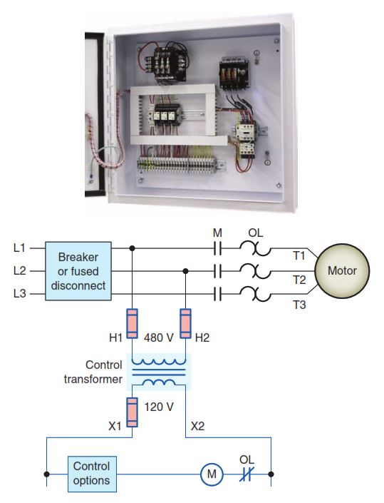
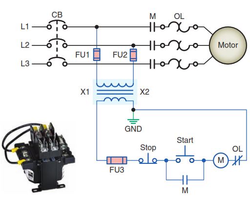
Step-down control transformers are installed when the control circuit components are not rated for the line voltage. Figure 3-27 shows the typical connection for a step-down motor control transformer. The primary side (H1 and H2) of the control transformer will be the line voltage (240 V), while the secondary voltage (X1 and X2) will be the voltage required for the control components (120 V).
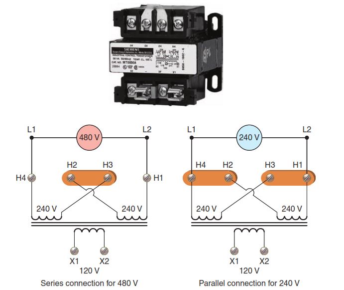
Single-, dual-, and multitap primary control transformers are available. The versatile dual- and multitap primary transformers allow reduced control voltage from a variety of voltage sources to meet a wide array of applications. Figure 3-28 shows the connections for a typical dual primary transformer used to step 240 or 480 V down to 120 V.
- The primary connections on the transformer are identified as H1, H2, H3, and H4.
- The transformer coil between H1 and H2 and the one between H3 and H4 are rated for 240 V each.
- The low-voltage secondary connections on the transformer, X1 and X2, can have 120 V from either a 480 or 240 V line.
- If the transformer is to be used to step 480 V down to 120 V, the primary windings are connected in series by a jumper wire or metal link.
- When the transformer is to be used to step 240 V down to 120 V, the two primary windings must be connected in parallel with each other.
The control transformer secondary can be grounded or ungrounded. Where grounding is provided, the X2 side of the circuit common to the coils must be grounded at the control transformer. This will ensure that an accidental ground in the control circuit will not start the motor, or make the stop button or control inoperative. An additional requirement for all control transformers is that they be protected by fuses or circuit breakers. Depending on the installation, this protection can be placed on the primary, secondary, or both sides of the transformer. Figure 3-29 shows fuse protection for both the primary and secondary of the transformer and the correct ground connection for a grounded control system. The fuses must be properly sized for the control circuit. Section 430.72 of the Code lists requirements for the protection of transformers used in motor control circuits
Three-Phase Transformers
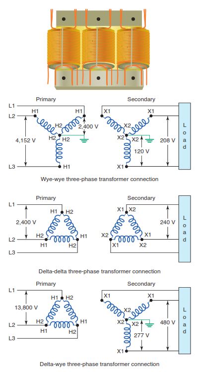
Large amounts of power are generated and transmitted using high-voltage three-phase systems. Transmission voltages may be stepped down several times before they reach the motor load. This transformation is accomplished using three-phase wye- or delta-connected transformers or a combination of the two. Figure 3-30 illustrates some of the common three-phase wye and delta transformer connections. The connections are named after the way the windings are connected inside the transformer. Polarity markings are fixed on any transformer and the connections are made in accordance with them
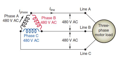
The transformers supplying motor loads can be con-nected on the load (secondary) side either in delta or in wye configuration. Two types of secondary distribution systems commonly used are the three-phase three-wire system and three-phase four-wire system. In both, the secondary volt-ages are the same for all three phases. The three-phase three-wire delta system is used for balanced loads and consists of three transformer windings connected end to end. Figure 3-31 shows a typical three-phase, three-wire delta transformer connection supplying power to a three-phase motor load. For a delta-connected transformer:
- The phase voltage (Ephase) of the transformer secondary is always the same as the line voltage (Eline) of the load.
- The line current (Iline) of the load is equal to the phase current (Iphase) of the transformer secondary multiplied by 1.73
kVA (transformer) = (Iline × Eline × 1.732) / 1,000
- The constant 1.73 is the square root of 3 and is used because the transformer phase windings are 120 electrical degrees apart
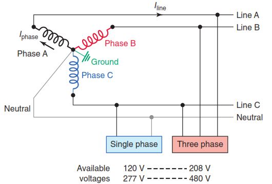
The other commonly used three-phase distribution is the three-phase, four-wire system. Figure 3-32 shows a typical wye-connected three-phase, four-wire distribution system. The three phases connect at a common point, which is called the neutral. Because of this, none of the windings are affected by the other windings. Therefore, the wye three-phase, four-wire system is used for unbalanced loads. The phases are 120 electrical degrees apart; however, they have a common point. For a wye transformer connected transformer:
- The phase-to-phase voltage is equal to the phase-to-neutral voltage multiplied by 1.73.
- The line current is equal to the phase current
kVA (transformer) = (Iline × Eline × 1.732) / 1000
- Common arrangements are 480Y/277 V and 208Y/120 V.
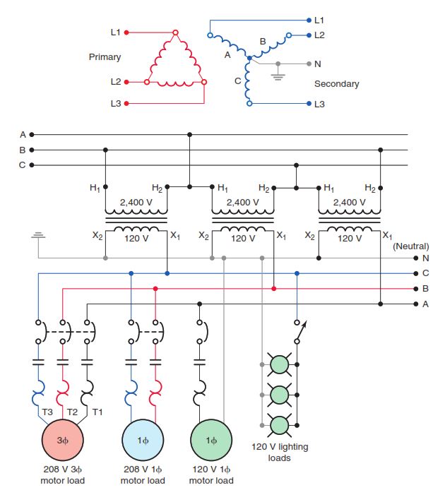
The delta-to-wye configuration is the most com-monly used three-phase transformer connection. A typical delta-to-wye voltage transformation is illustrated in Figure 3-33. The secondary provides a neutral point for supplying line-to-neutral power to single-phase loads. The neutral point is also grounded for safety reasons. Three-phase loads are supplied at 208 V, while the voltage for single-phase loads is 208 V or 120 V. When the transformer secondary supplies large amounts of unbalanced loads, the delta primary winding provides a better current balance for the primary source.
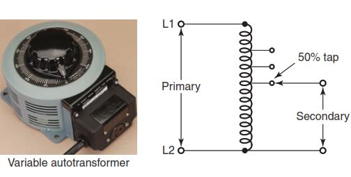
The autotransformer, shown in Figure 3-34, is a transformer consisting of a single winding with electrical connection points called taps.
- Each tap corresponds to a different voltage so that, in effect, a portion of the same inductor acts as part of both the primary and secondary windings.
- There is no electrical isolation between the input and output circuits, unlike the traditional two-winding transformer.
- The ratio of secondary to primary voltages is equal to the ratio of the number of turns of the tap they connect to. For example, connecting at the 50 percent tap (middle) and bottom of the autotransformer output will halve the input voltage.
- Because it requires both fewer windings and a smaller core, an autotransformer for some power applications is typically lighter and less costly than a two-winding transformer.
- A variable autotransformer is one in which the output connection is made through a sliding brush and is widely used where adjustable AC voltages are required.
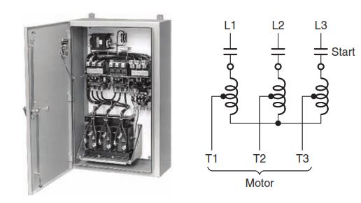
An autotransformer motor starter, such as shown in Figure 3-35, reduces inrush motor current by using a three-coil autotransformer in the line just ahead of the motor to step down the voltage applied to the motor terminals. By reducing the voltage, the current drawn from the line is reduced during start-up. During the starting period, the motor is connected to the reduced-voltage taps on the autotransformer. Once the motor has accelerated, it is automatically connected to full-line voltage.
Instrument Transformers
Instrument transformers are small transformers used in conjunction with instruments such as ammeters, volt-meters, power meters, and relays used for protective purposes. These transformers step down the voltage or current of a circuit to a low value that can be effectively and safely used for the operation of instruments. Instrument transformers also provide isolation between the instrument and the high voltage of the power circuit.
A typical current and potential transformer connection diagram is shown in Figure 3-36.
- Polarity marks are shown to ensure correct wiring.
- Low-resistance current elements of the instruments are connected in series, while voltage inputs are connected in parallel.
- Polarity is not a consideration on single-element devices such as an ammeter or voltmeter but is essential for proper operation of three-phase metering and other protective and control devices that require proper polarity connections.
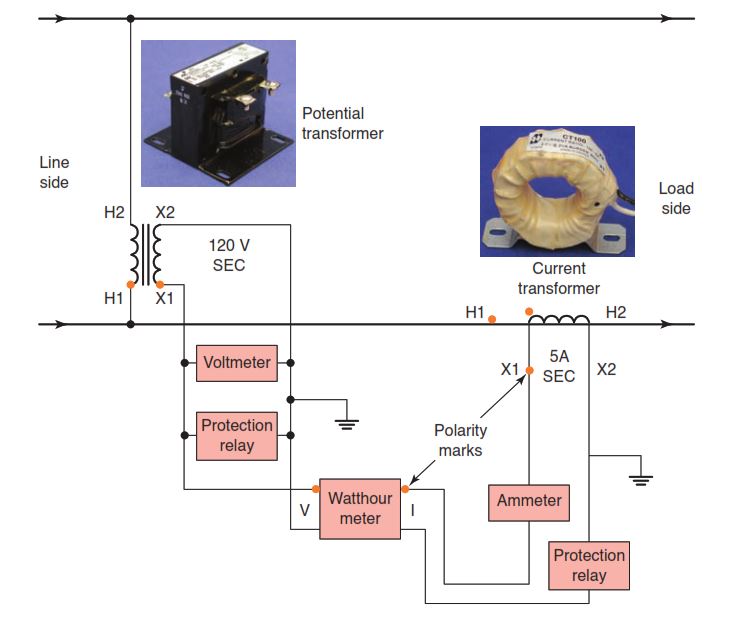
A potential (voltage) transformer operates on the same principle as a standard power transformer. The main dif-ference is that the capacity of a potential transformer is relatively small compared to power transformers. Potential transformers have typical power ratings of from 100 VA to 500 VA. The secondary low-voltage side is usually wound for 120 V, which makes it possible to use standard instruments with potential coil ratings of 120 V. The primary side is designed to be connected in parallel with the circuit to be monitored.
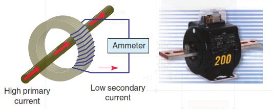
A current transformer (CT) is a type of instrument transformer that is designed to provide a current in its secondary that is accurately proportional to the current flowing in its primary. Current transformers are used when the magnitude of AC currents or voltage exceeds the safe value of current of measuring instruments. Figure 3-37 illustrates how a current transformer operates.
- The primary is a line conductor connected in series that passes through the center of the transformer.
- • The secondary winding consisting of many turns is designed to produce a standard 5 A output when its rated current is flowing in the primary.
- Current transformers are specified by a current ratio such as 5:2000, where 200 A of primary current will result in 5 A of secondary output current
- The secondary load (ammeter) of the current transformer is called the burden to distinguish it from the load of the circuit whose current is being measured.
All current transformers have subtractive polarity. Recall that on subtractive polarity transformers, the H1 primary lead and the X1 secondary lead will be on the same side of the transformer, as illustrated in Figure 3-38. The secondary circuit of a current transformer should never be opened when there is current in the primary
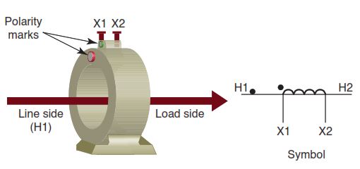
winding. If the secondary is not connected to a burden load, the transformer acts to step up the secondary voltage to a dangerous level, because of the high turns ratio. For this reason, a current transformer should always have its secondary (X1–X2) shorted when not connected to an external load. In applications that depend on the interaction of two instruments, such as a watthour meter or protective relay, it is essential that the polarity of both current and potential transformers be known and that definite relationships be maintained