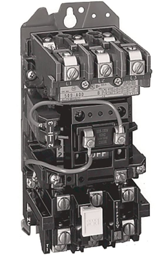
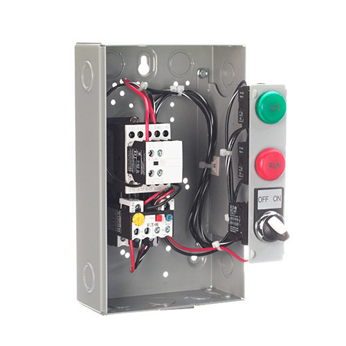
A magnetic contactor is a device that uses magnetism to repeatedly switch on or off an electric power circuit. It works in a similar way to an electromechanical relay, which also has contacts that move when the coil is energized. However, contactors are designed to handle electric power circuit loads of more than 15 A without getting damaged, unlike relays. A common NEMA magnetic contactor for controlling AC motor loads without overload protection or with separate overload protection. It has three power contacts and one auxiliary contact that is normally open and holds the circuit closed when using three-wire pushbutton control.
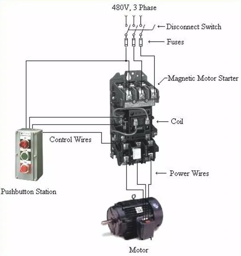
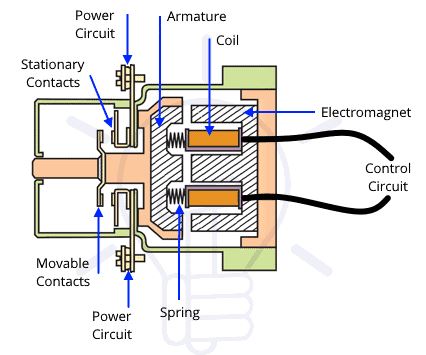
There are two circuits involved with the operation of a magnetic contactor: the control circuit and the power circuit. The control circuit is connected to the coil, and the power circuit is connected to the main power contacts.
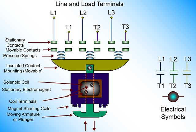
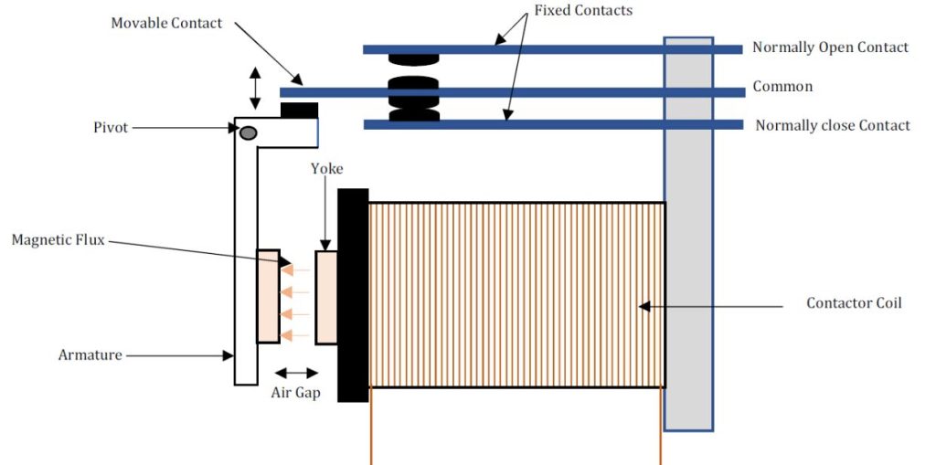
- When voltage is applied to the terminals of the coil, the current flows through the coil, creating a magnetic field.
- The coil, in turn, magnetizes the stationary iron frame, turning it into an electromagnet.
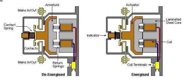
- The electromagnet draws the armature toward it, pulling the movable and stationary contacts together.
- Power then flows through the contactor from the line side to the load side.
- Generally, a contactor is available in two-, three-, or four-pole contact configurations.
Switching Loads
Contactors are electromechanical devices that are used to control high-power loads. They are often used in conjunction with pilot devices, which are low-current devices that are used to activate the contactor coil. The contactor coil, when energized, closes the contactor contacts, allowing current to flow through the load. In this application, the contactor coil is connected to level and temperature sensors, which are used to automatically control the power contacts to the solenoid and heating element loads. The contactor acts as a switch, opening and closing the circuit to the solenoid and heating element loads based on the signals from the level and temperature sensors.
A contactor is a device that can switch motor loads when they have separate overload protection. One of the most common applications for a contactor is to work with an overload relay module to control an AC motor starter. The motor can be controlled by either two-wire or three-wire control circuits. Two-wire control is often used for automatic operations, such as pumps, electric heaters, and air compressors, where the motor is started and stopped by a pilot device as needed. Three-wire control is similar to two-wire control, but it has an extra set of contacts to keep the circuit energized. Three-wire control is usually used for motors that are controlled by start/stop push buttons that are pressed momentarily. In this case, the push buttons are used to turn on or off the contactor coil. Start/stop push buttons are typically used to start and stop the system processes.
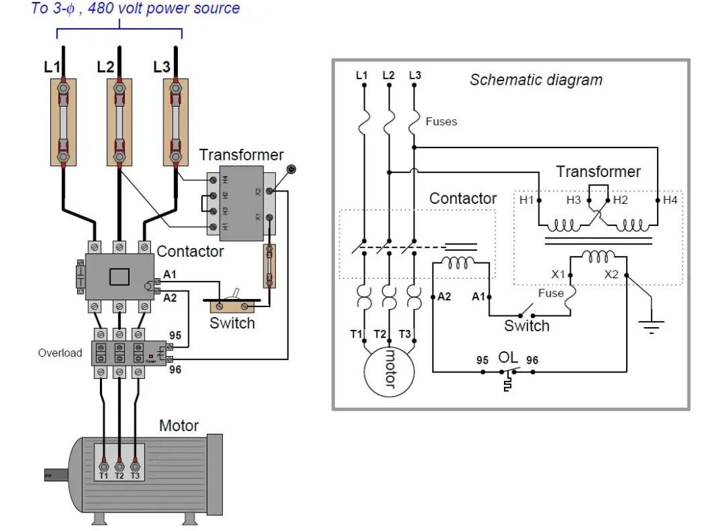
A contactor can switch high voltage loads without exposing the operator to any danger. To do this, a control transformer is used to reduce the AC voltage level for the control circuit. The control circuit voltage can be 12, 24, or 120 V, while the line voltage can be 208, 230, 240, 460, 480, or 600 V. The contactor coil voltage and the control circuit voltage must be the same.
The contactor has auxiliary contacts that are used for interlocking, holding, and status indication in the control circuits. They have a lower current rating than the main contacts that switch the power to the load. The circuit works as follows:
- The control transformer lowers the 480 V line voltage to 120 V for the control circuit.
- The three-wire control circuit switches the power to the heater elements.
- When the on/off switch is closed, the heat on push button is pressed to turn on the contactor coil M.
- The main contacts M-1, M-2, and M-3 close and power the heater elements at line voltage.
- The auxiliary contact M-4 closes and keeps the contactor coil on by bypassing the heat on push button.
- At the same time, the auxiliary contact M-5 opens and turns off the green (off) pilot light and contact M-6 closes and turns on the red (on) pilot light.
- Pressing the heat off push button or opening the on/off switch will turn off the contactor coil and return the circuit to its off state.
Definite-purpose contactors are designed for specific applications, such as controlling electrical loads in air conditioning, refrigeration, heating, data processing, and lighting systems. Lighting contactors are well-suited for switching lamps in various environments. They can be used in office buildings, industrial plants, hospitals, stadiums, and airports to control tungsten, fluorescent, and mercury arc lamps. Lighting contactors are available in two types: electrically held and mechanically held. Electrically held contactors require continuous power to keep the contacts closed, while mechanically held contactors only need a brief pulse of power to change state and are held in place by a mechanical latch. Mechanically held contactors are more energy-efficient and operate quieter than electrically held contactors.
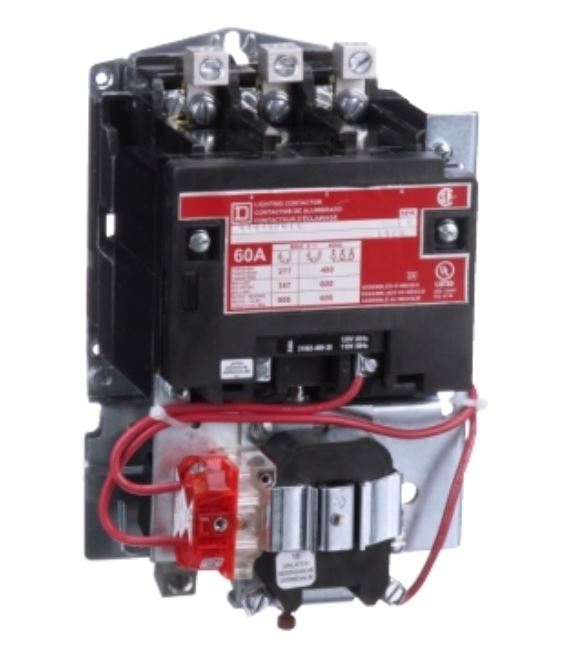
Figure below illustrates the wiring diagram for a mechanically held lighting contactor with a single operating coil. The coil is momentarily energized to toggle the contactor’s state. In this application, the contactor is controlled by two remotely located three-position momentary control stations. The contactor can also be interfaced with various automatic control devices, such as programmable logic controllers (PLCs) and energy management systems.

Contactor Assemblies
The operating mechanisms of magnetic contactors can be classified into three types: bell-crank, horizontal-action, and clapper. These are shown in Figure below. The operating mechanisms should be checked regularly to make sure they work properly and smoothly. The operating mechanism has a magnetic circuit made of soft steel that has high permeability and low residual magnetism. The coil creates a magnetic force that pulls the armature against the gravity and the spring force of the contacts.
- Coils with signs of overheating (cracked, melted, or burned insulation) must be replaced. To measure coil resistance, disconnect one lead and use an ohmmeter on its lowest range. A faulty coil will read zero (short circuit) or infinity (open circuit).
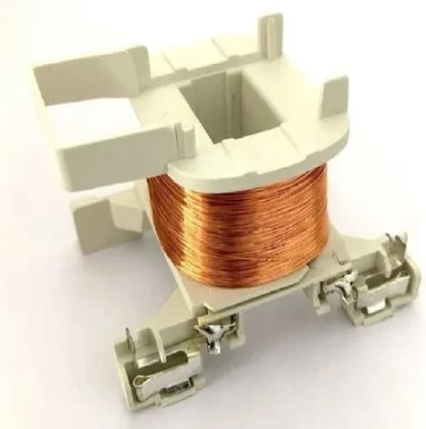
- Contactor coils have insulated windings designed to generate the necessary ampere-turns for operation. Since contactors are used for different voltages, coil voltages must match the available control voltage. The operating range is 85-110% of rated voltage. Voltage variations greater than ±5% accelerate contact wear and reduce coil lifespan. This is because higher voltages increase the closing speed of the electromagnet, while lower voltages decrease the closing speed. Both factors contribute to contact wear and erosion.
- Magnetic coil voltage specifications include rated voltage, pickup voltage, hold-in voltage, and dropout voltage. Rated voltage is the coil supply voltage and must match the control circuit voltage. Pickup voltage is the voltage required to overcome the mechanical forces preventing contact closure (gravity, spring tension). Hold-in voltage is the voltage required to keep the contacts closed after pickup voltage is reached (usually lower than pickup voltage). Electrically held contactors are sensitive to voltage dips. Dropout voltage is the voltage below which the magnetic field is too weak to hold the contacts closed.
- AC and DC contactor coils with the same voltage ratings are not interchangeable because DC coil current is limited by resistance, while AC coil current is limited by resistance and inductive reactance (impedance). DC contactor coils have more turns and higher resistance than their AC counterparts.
- In DC-operated coils, the current flow upon closing is the same as the energized current flow. However, this is not the case for AC-operated coils. With a de-energized AC coil, there is an air gap in the magnetic path because the armature is not pulled in. When the contactor closes, the air gap is closed, increasing the inductive reactance and decreasing the current. This results in a high inrush current for closing and a lower holding current. AC coil inrush current can be 5-20 times the sealed current.
When an inductive load, such as a contactor coil, is de-energized, a high voltage spike is generated. These spikes can reach several thousand volts and damage sensitive electronic components. RC suppression modules are used to suppress these voltage spikes. RC suppression modules are wired in parallel with the contactor coil. The resistor and capacitor in the RC module slow down the rate of rise of the transient voltage.
AC contactors experience changes in the magnetic field surrounding them. This causes the contactor to buzz or chatter. Shading coils are used to prevent this buzzing and chattering. Shading coils are mounted on the contactor coil. They create an auxiliary magnetic attraction that helps to hold the armature in place. Shading coils are made of a single turn of conducting material. A broken or open shading coil will cause the contactor to become noisy.
The core and armature of an AC contactor are laminated. This is because eddy currents are generated in the core and armature when AC flows through the contactor coil. Eddy currents are small currents that flow in the opposite direction of the main current. They waste energy and generate heat. Lamination reduces eddy current losses.
Misalignment or obstruction of the armature can cause increased current flow in the contactor coil. This can damage the coil. Misalignment can be caused by pivot wear, binding, corrosion, or dirt buildup. It can also be caused by pole face damage. Misalignment will cause the contactor to hum. A broken shading coil will also cause the contactor to hum.
Silver contacts are commonly used in contactors. Silver contacts have a low electrical resistance. They are also corrosion-resistant. Silver contacts are often brazed or welded to copper contacts. The silver carries the current, and the copper carries the heat. Silver contacts should not be filed. They should also not be cleaned, as the black discoloration is a good conductor of electricity.
Contactors have auxiliary contacts that are used to control other circuits. Auxiliary contacts have a lower current rating than the main contacts. They are actuated by the same armature as the main contacts. Auxiliary contacts can be either normally open or normally closed.
Arc Suppression
Contacts wear out because of the electric arc that happens when they open under load. When the contacts open, there is still current flowing between them if the voltage is high enough. The current flows through the air that is ionized by the arc. The arc gets weaker as the contacts get farther apart, because the resistance of the air increases and the current decreases. The voltage needed to keep the arc going also increases. At some point, the line voltage is not enough to sustain the arc and it stops. The arc can make the contacts very hot and melt or vaporize the metal on their surfaces. This is why it is better to stop the arc as soon as possible; otherwise, the arc will damage the contacts. Most contactors have some kind of arc chamber that helps to put out the arc.
Some of the main factors that affect the contact arcing are:
- The voltage and current that are switched by the contacts. The higher the circuit voltage and current, the faster the gap between the contacts becomes a conductive path when they open.
- The kind of voltage (AC or DC) that is switched. It is easier to stop an AC arc than a DC arc. An AC arc will stop by itself when the AC cycle goes through zero. A DC arc will not stop by itself because the current is always in one direction and there is no natural way to stop it.
- The load type (resistive or inductive). For resistive loads, the arc duration depends mainly on how fast the contacts separate. For inductive loads, the energy stored in the magnetic field keeps the current going and causes voltage spikes. Inductive loads are less problematic in AC circuits than in DC circuits.
- The speed of the contactor operation. The faster the contacts separate, the sooner the arc will stop.
When contactors are closing, arcing can also happen, for example, if the voltage is high enough to make an arc across the gap between the contacts before they touch. Another way this can happen is if one contact has a rough edge that melts when it touches the other contact and makes a path for current to flow. In both cases, the arc stops when the contacts are fully closed.
One big difference between AC and DC contactors is how they deal with the arcs that are formed when the contacts open and close under load. To stop arcing in DC circuits, the contactor is made so that the contacts will open fast and with enough space to stop the arc as soon as possible. DC contactors are bigger than AC contactors with the same rating to have more space between the contacts (Figure 6-18). It is also important to close DC contacts fast to avoid some of the same problems that happen when they open. That is why DC contactors are designed to work faster than AC contactors.
AC contactors use arc chutes that are similar to the ones used in DC contactors. But most DC contactors also use magnetic blowout coils to help stop the arcs. Blowout coils are thick copper coils that are above the contacts and connected with them. When current flows through the blowout coil, it makes a magnetic field between the contacts that breaks the arc. The arc also makes a magnetic field around itself. The magnetic fields of the arc and the blowout coil push each other away. This makes the arc longer and longer until it stops.
Blowout coils usually work well and do not cause problems if they are used within their voltage and current limits. Arc chutes are always exposed to the high heat of arcing and may eventually get burned, making the arc connect to the metal parts of the blowout. So, arc chutes should be checked regularly and changed before they get burned through.
As part of keeping the contactors in good condition, big contactors should be inspected from time to time for how much the contacts are worn, how much the contacts move, how well the shunt terminals are connected, how freely the armature moves, how the blowout structure is, how the blowout coil connections are, how the coil structure is, how much pressure the contact springs have, and how much space there is between the contacts. Normally the contacts stay clean because of the small rubbing and burning that happen during normal use. Copper contacts, which some contactors still have, should be cleaned to lower the contact resistance. Contacts that are worn should always be changed in pairs to make sure that they touch each other well. High contact resistance makes the contacts too hot and also makes a big voltage drop across the contacts, which means less voltage goes to the load.
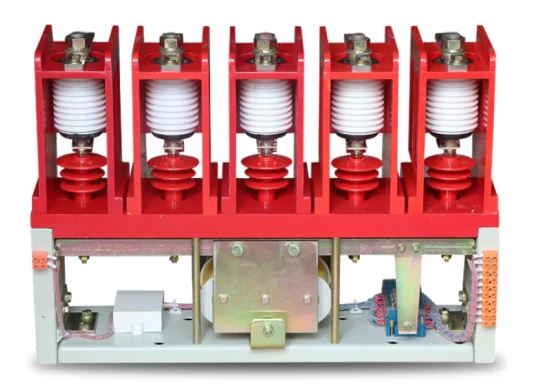
A vacuum contactor turns on and off power contacts inside a closed vacuum bottle. The vacuum is better than air for stopping the arc because there is no air to make it keep going, so the arc stops faster. The arc is also separated from dust and corrosion inside the vacuum bottles. Compared to normal air contactors they last longer electrically and are better for switching devices in situations with a lot of switching, for starting heavy loads, and for line voltages above 600 V.