Manual motor stater
Manual starters are characterized by the fact that the operator must go to the location of the starter to initiate any change of action. There are several different types of manual starters. Some look like a simple toggle switch with the addition of an overload heater. Others are operated by push buttons and may or may not be capable of providing low voltage protection.
Fractional Horsepower Single Phase Starters
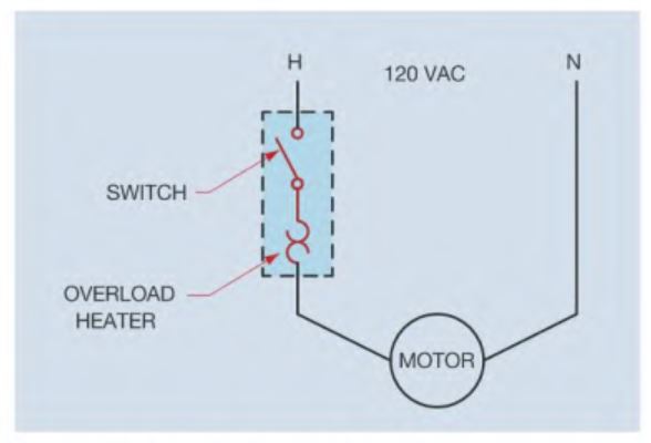
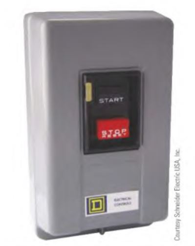
One of the simplest manual motor starters resembles a simple toggle switch with the addition of an overload heater. The toggle switch lever is mounted on the front of the starter and is used to control the on and off operation of the motor. In addition to being an on and off switch, it also provides overload protection for the motor. An overload heater symbol has been added to the photograph to indicate where the overload heater should be connected. When current flows, the heater produces heat in proportion to the amount of motor current. If the heater is sized correctly, it will never get hot enough to open the circuit under normal operating conditions. If the motor should become overloaded, however, current increases causing a corresponding increase in the heat production by the heater. If the heat becomes great enough, it causes a mechanical mechanism to trip and open the switch contacts and disconnect the motor from the power line. If the starter trips on overload, the switch lever moves to a center position. The starter must be reset before the motor can be restarted by moving the lever to the full OFF position. This action is basically the same as resetting a tripped circuit breaker. The starter shown in this example has only one line contact and is generally used to protect motors intended to operate on 120 volts.
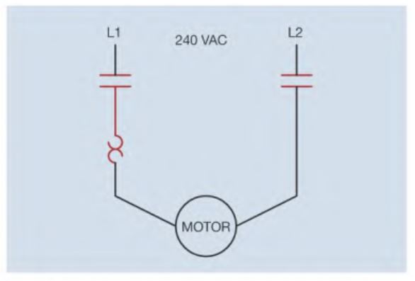
Starters that are intended to protect motors that operate on 240 volts should contain two load contacts. Although a starter that contains only one contact would control the operation of a 240-volt motor, it could create a hazardous situation. If the motor were switched off and an electrician tried to disconnect the motor, one power line would still be connected directly to the motor. Section 430.103 of the National Electrical Code® (NEC®) requires that a disconnecting means open all ungrounded supply conductors to a motor.
Manual starters of this type are intended to control fractional horsepower motors only. Motors of 1 horsepower or less are considered fractional horsepower. Starters of this type are across-the-line starters. This means that they connect the motor directly to the power line. Some motors can draw up to 600 percent of rated full load current during starling. These starters generally do not contain large enough contacts to handle the current surge of multi-horsepower motors.
Another factor to consider when using a starter of this type is that it does not provide low voltage release. Most manual starters are strictly mechanical devices and do not contain an electrical coil. The contacts are mechanically opened and closed. This simply means that if the motor is in operation and the power fails, the motor will restart when the power is restored. This can be an advantage in some situations where the starter controls unattended devices such as pumps, fans, blowers, air conditioning, and refrigeration equipment. This feature saves the maintenance electrician from having to go around the plant and restart all the motors when power returns after a power failure.
This automatic restart feature can also be a disadvantage on equipment such as lathes, milling machines, saws, drill presses, and any other type of machine that may have an operator present. The unexpected and sudden restart of a piece of equipment could cause injury.
Mounting
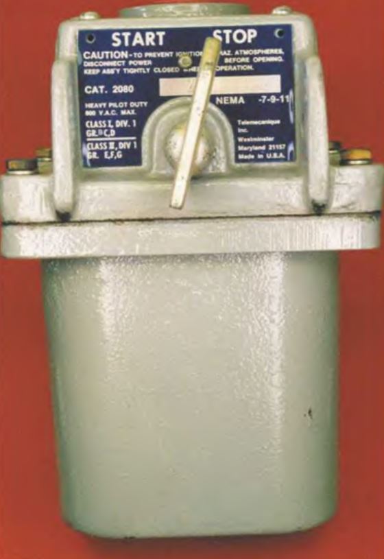
Like larger starters, fractional horsepower starters can be obtained in different enclosures. Some are simple sheet metal and are intended to be mounted on the surface or on a piece of machinery. If the starter is to be mounted in an area containing hazardous vapors or gasses, it may require an explosion-proof enclosure. Other areas that are subject to high moisture
may require a waterproof enclosure.
Mounting this type of starter is generally very simple because it requires very little space. The compact design of this starter permits it to be mounted in a single gang switch or conduit box or directly on a piece of machinery. The open type starter can be mounted in the wall and covered with a single gang switch cover plate. The ON and OFF markings on the switch lever make it appear to be a simple toggle switch.
Automatic Operation
It is sometimes necessary to combine the manual starter with other sensing devices to obtain the proper control desired. When using some type of sensing pilot device to directly control the operation of a motor, you must make sure that the pilot device is equipped with contacts that can handle the rated current of the motor. These devices are generally referred to as line voltage devices. Line voltage devices have larger contacts than sensing pilot devices intended for use in a motor control circuit that employs a magnetic motor starter. The smaller pilot devices intended for use with magnetic motor starters have contacts that are typically rated from 1 to 3 amperes. Line voltage devices may have contacts rated for 15 to 20 amperes. In this circuit, a line voltage thermostat is used to control the operation of a blower motor. When the temperature rises to a sufficient level, the thermostat contact close, connecting the motor directly to the power line if the manual starter contacts are closed. When the temperature drops, the thermostat contact opens and turns off the motor
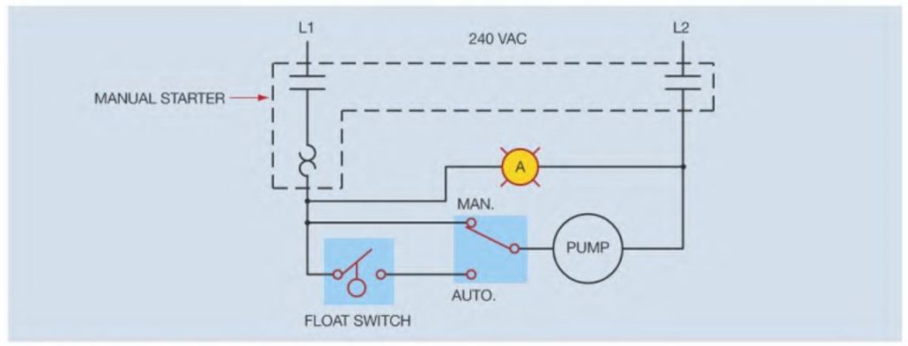
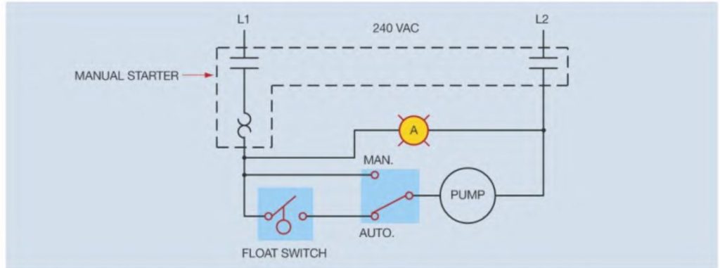
In this circuit a manual/automatic switch is used to select either manual or automatic operation of a pump. The pump is used to fill a tank when the water falls to a certain level. The schematic is drawn to assume that the tank is full of water during normal operation. In the manual position, the pump is controlled by turning the starter on or off. An amber pilot light indicates when the manual starter contacts are closed or turned on. If the manual/automatic switch is moved to the automatic position, a line voltage float switch controls the operation of the pump motor. When water in the tank drops low enough, the float switch contact closes and starts the pump motor. When water rises to a high enough level, the float switch contact opens and disconnects the pump motor from the line.
Manual Push Button Starters
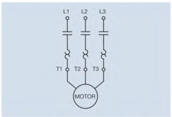
Manual push button line voltage starters are manufactured with two or three line voltage contacts. The two contact models are intended to control single phase motors that operate on 240 volts, or direct current motors. The starters that contain three contacts are intended to control three phase motors. Push button type manual starters are integral, not fractional, horsepower starters. Generally, they can control single phase motors rated up to 5 horsepower, direct current motors up to 2 horsepower, and three phase motors up to 10 horsepower.
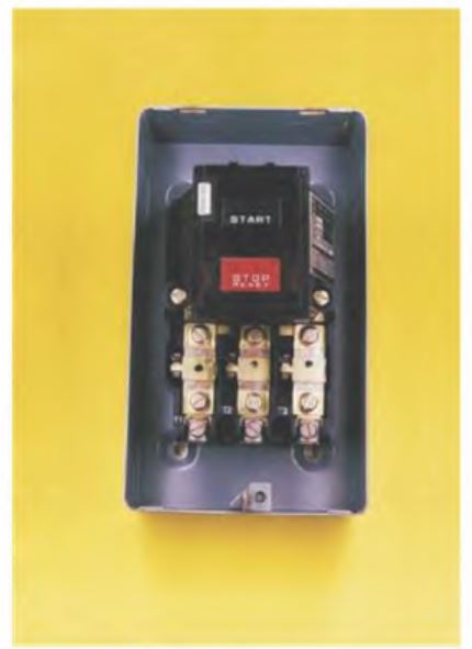
If any one of the overloads should trip, a mechanical mechanism opens the load contacts and disconnects the motor from the line. Once the starter has tripped on overload, it must be reset before the motor can be restarted. After allowing enough time for the overload heaters to cool, resetting the starter is accomplished by pressing the STOP push button with more than normal pressure. This extra pressure causes the mechanical mechanism to reset so that the motor can restart when the START push button is pressed. These starters are economical and are generally used with loads that are not started or stopped at frequent intervals. Although this type of starter provides overload protection, it does not provide low voltage release. If the power should fail and then be restored, the motor this starter controls will restart without warning.
Manual Starter with Low Voltage Release
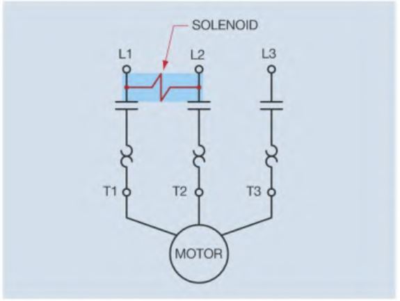
Integral horsepower manual starters with low voltage release will not restart after a power failure with out being reset. This is accomplished by connecting a solenoid across the incoming power lines. As long as power is supplied to the starter, the solenoid holds a spring-loaded mechanism in place. As long as the mechanism is held in place, the load contacts can be closed when the START button is pressed. If the power is interrupted, the spring-loaded mechanism mechanically opens the contacts and prevents them from being reclosed until the starter has been manually reset. This starter will not operate unless power is present at the line terminal. This starter should not be confused with magnetic starters controlled by a coil. Magnetic type starters are designed to be used with other pilot control devices that control the operation of the starter.
manual starter
TroubIe shooting
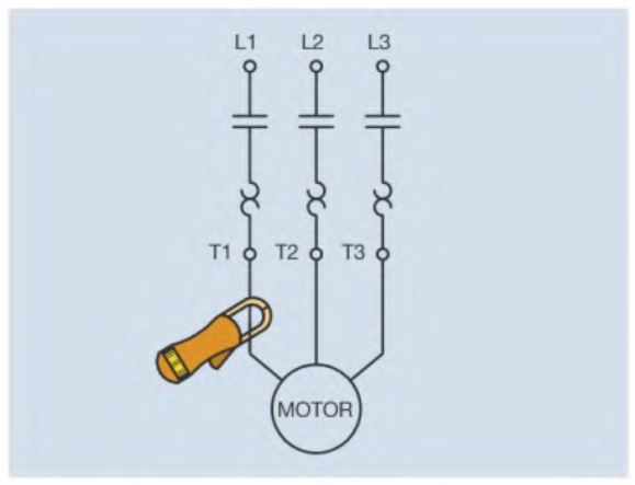
Anytime a motor has tripped on overload, the electrician should check the motor and circuit to determine why the overload tripped. The first step is generally to determine whether the motor is actually overloaded. Some common causes of motor overloads are bad bearings in either the motor or the load the motor operates. Shorted windings in the motor can cause the motor to draw excessive current without being severe enough to blow a fuse or trip a circuit breaker. The simplest way to determine if the motor is overloaded is to find the motor full load current on the nameplate and then check the running current with an ammeter. If checking a single phase motor, it is necessary to check only one of the incoming lines. If checking a three phase motor, each line should be checked individually. The current flow in each line of a three phase motor should be relatively the same. A small amount of variation is not uncommon, but if the current is significantly different in any of the lines, it is an indication of internally shorted windings. Overloads are generally set to trip at 115 percent to 125 percent of motor full load current, depending on the motor. If the ammeter reveals that the motor is drawing excessive current, the reason must be determined before the motor can be put back into operation.
Excessive current is not the only cause for an overload trip. Thermal overloads react to heat. Any heat source can cause an overload to trip. If the motor is not drawing an excessive amount of current, the electrician should determine any other sources of heat. Loose connections are one of the greatest sources of heat. Check the wires for insulation that has been overheated close to terminal screws. Any loose connection on the starter can cause an overload trip. Make sure that all connections are tight. Another source of heat is ambient or surrounding air temperature. In hot climates, the surrounding air temperature combined with the heat caused by motor current can be enough to cause the overload to trip. It may be necessary to set a fan that blows on the starter to help remove excess heat. Manual starters that are installed in a switchbox inside a wall are especially susceptible to ambient temperature problems. In this case it may be necessary to install some type of vented cover plate.