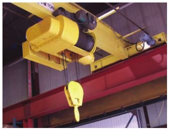
Industrial applications use DC motor because the speed–torque relationship can be easily varied. DC motor applications include cranes (Figure 2-24), conveyors, elevators, and material handling processes.
- DC motors feature a speed, which can be controlled smoothly down to zero, immediately followed by acceleration in the opposite direction.
- In emergency situations, DC motors can supply over five times rated torque without stalling.
- Dynamic braking (DC motor-generated energy is fed to a resistor grid) or regenerative braking (DC motor-generated energy is fed back into the DC motor supply) can be obtained with DC motors on applications requiring quick stops, thus eliminating the need for, or reducing the size of, a mechanical brake.
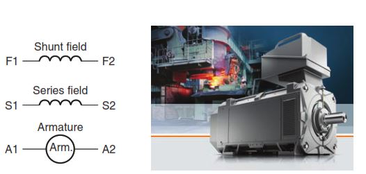
Figure 2-25 shows the symbols used to identify the basic parts of a direct current (DC) compound motor. The rotating part of the motor is referred to as the armature; the stationary part of the motor is referred to as the stator, which contains the series field winding and the shunt field winding. In DC machines A1 and A2 always indicate the armature leads, S1 and S2 indicate the series field leads, and Fl and F2 indicate the shunt field leads.
It is the kind of field excitation provided by the field that distinguishes one type of DC motor from another; the construction of the armature has nothing to do with the motor classification. There are three general types of DC motors, classified according to the method of field excita-tion as follows:
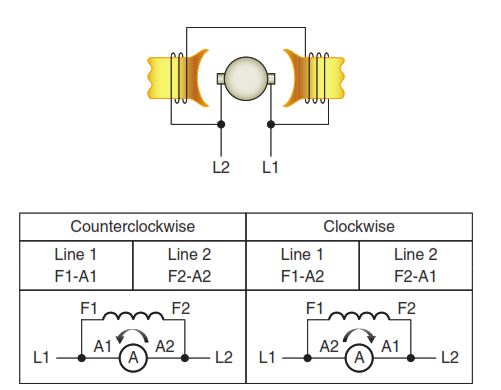
- A shunt DC motor (Figure 2-26) uses a comparatively high resistance shunt field winding, made up of many turns of fine wire, connected in parallel (shunt) with the armature.
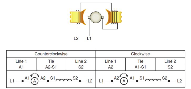
- A series DC motor (Figure 2-27) uses a very low resistance series field winding, made up of very few turns of heavy wire, connected in series with the armature.
- A compound DC motor (Figure 2-28) uses a combination of a shunt field (many turns of fine wire) in parallel with the armature, and series field (few turns of heavy wire) in series with the armature.
All connections shown in Figures 2-26, 2-27, and 2-28 are for counterclockwise and clockwise rotation facing the end opposite the drive (commutator end). One purpose of applying markings to the terminals of motors according to a standard is to aid in making connections when a predictable rotation direction is required. This may be the case when improper rotation could result in unsafe operation or damage. Terminal markings are normally used to tag only those terminals to which connections must be made from outside circuits.

The direction of rotation of a DC motor depends on the direction of the magnetic field and the direction of current flow in the armature. If either the direction of the field or the direction of current flow through the armature is reversed, the rotation of the motor will reverse. However, if both of these factors are reversed at the same time, the motor will continue rotating in the same direction.