The construction of the electromagnetic part of a relay or contactor greatly depends on whether it is to be oper ated by direct or alternating current. Relays and contactors that are operated by direct current generally contain solid core materials, while those intended for use with alternating current contain laminated cores. The main reason is the core losses associated with alternating current caused by the continuous changing of the electromagnetic field.
Core Losses
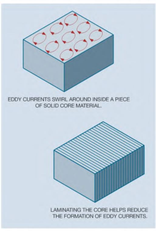
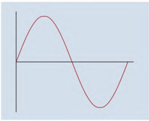
This continuous change of both amplitude and polarity of the magnetic field causes currents to be induced into the metal core material. These currents are called eddy currents because they are similar to eddies (swirling currents) found in rivers. Eddy currents tend to swirl around inside the core material producing heat. Laminated cores are constructed with thin sheets of metal stacked together. A thin layer of oxide forms between the laminations. This oxide is an insulator and helps reduce the formation of eddy currents.
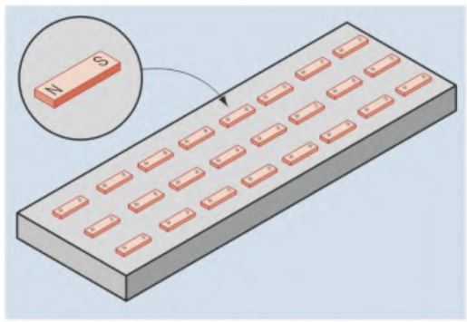
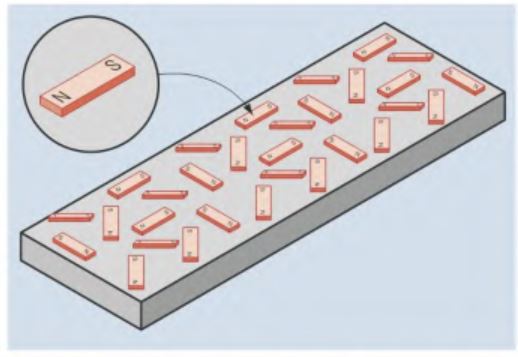
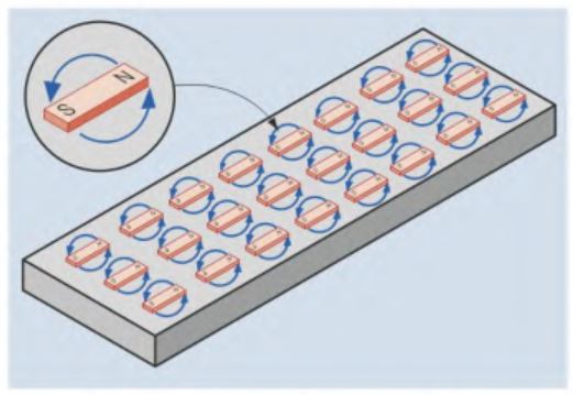
Another type of core loss associated with alternating current devices is called hysteresis loss. Hysteresis loss is caused by the molecules inside magnetic materials changing direction. Magnetic materials such as iron or soft steel contain magnetic domains or magnetic molecules. In an unmagnetized piece of material, these magnetic domains are not aligned in any particular order. If the metal becomes magnetized, the magnetic molecules or domains align themselves in an orderly fashion. If the polarity of the magnetic field is reversed, the molecules realign themselves to the new polarity. Although the domains realign to correspond to a change of polarity, they resist the realignment. The power required to cause them to change polarity is a power loss in the form of heat. Hysteresis loss is often referred to as molecular friction because the molecules are continually changing direction in an alternating current field. Hysteresis loss is proportional to the frequency. At low frequencies such as 60 Hz, it is generally so small that it is of little concern.
Shading Coils
As mentioned previously, all solenoid-type devices that operate on alternating current contain shading coils to prevent chatter. The current in an AC circuit is continually increasing from zero to a maximum value in one direction, returning to zero, and then increasing to a maximum value in the opposite direction. Because the current is continually falling to zero, the solenoid spring or gravity would continually try to drop out the armature when the magnetic field collapses. Shading coils provide a time delay for the magnetic field to prevent this from happening. As current increases from zero, magnetic lines of flux concentrate in the metal pole piece. This increasing magnetic field cuts the shading coil and induces a voltage into it. Because the shading coil or loop is a piece of heavy copper, it has a very low resistance. A very small induced voltage can cause a large amount of current to flow in the loop.
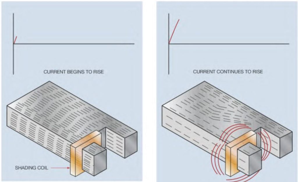
The current flow in the shading coil causes a magnetic field to be developed around the shading coil also. This magnetic field acts in opposition to the magnetic field in the pole piece and causes it to bend away from the shading coil. As long as the AC current is changing in amplitude, a voltage will be induced in the shading loop. When the current reaches its maximum or peak value, the magnetic field is no longer changing and no voltage is induced in the shading coil. Because the shading coil has no current flow, there is no magnetic field to oppose the magnetic field of the pole piece. When the current begins to decrease, the magnetic field of the pole piece begins to collapse. The collapsing magnetic field again induces a voltage into the shading coil. Because the collapsing magnetic field is moving in the opposite direction, the voltage induced in the shading coil causes current to flow in the opposite direction producing a magnetic field of the opposite polarity around the shading coil. The magnetic field of the shading coil now tries to maintain the collapsing magnetic field of the pole piece. This collapse causes the magnetic flux lines of the pole piece to concentrate in the shaded part of the pole piece. The shading coil provides a continuous magnetic field to the pole piece, preventing the armature from dropping out.

Control Relay Types
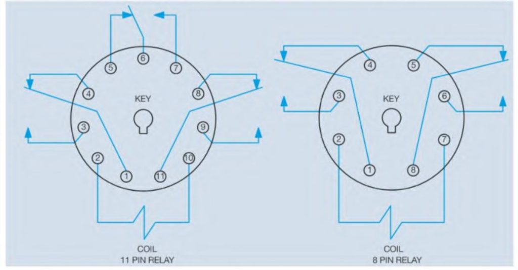
Control relays can be obtained in a variety of styles and types. Most have multiple sets of contacts and some are constructed in such a manner that their contacts can be set as either normally open or normally closed. This flexibility can be a great advantage. When a control circuit is being constructed, one relay may require three normally open contacts and one normally closed, while another may need two normally open and two normally closed contacts. Relays that are designed to plug into 8 or 11 pin tube or relay sockets are very popular for many applications. These sockets are often referred to as tube sockets because they were originally used for making connection to vacuum tubes. Relays of this type are relatively inexpensive and replacement is fast and simple in the event of failure. Because the relays plug into a socket, the wiring is connected to the socket, not the relay. Replacement is a matter of removing the defective relay and plugging in a new one. Both 8 and 11 pin relays can be obtained with different coil voltages. Coil voltages of 12 VDC, 24 VDC, 24 VAC, and 120 VAC are common. Their contact ratings generally range from 5 to 10 amperes depending on relay type and manufacturer. The pin numbers for 8 and 11 pin relays can be determined by holding the relay with the bottom facing you. Hold the relay so that the key is facing down. The 11 pin relay contains three separate single pole double throw contacts. Pins 1 and 4, 6 and 5, and 11 and 8 are normally closed contacts. Pins 1 and 3, 6 and 7, and 11 and 9 are normally open contacts. The coil is connected to pins 2 and 10. The 8 pin relay contains two separate single pole double throw contacts. Pins 1 and 4, and 8 and 5 are normally closed. Pins 1 and 3, and 8 and 6 are normally open. The coil is connected across pins 2 and 7.
Solid-State Relays
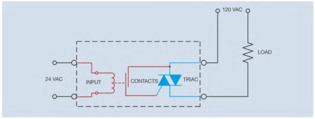
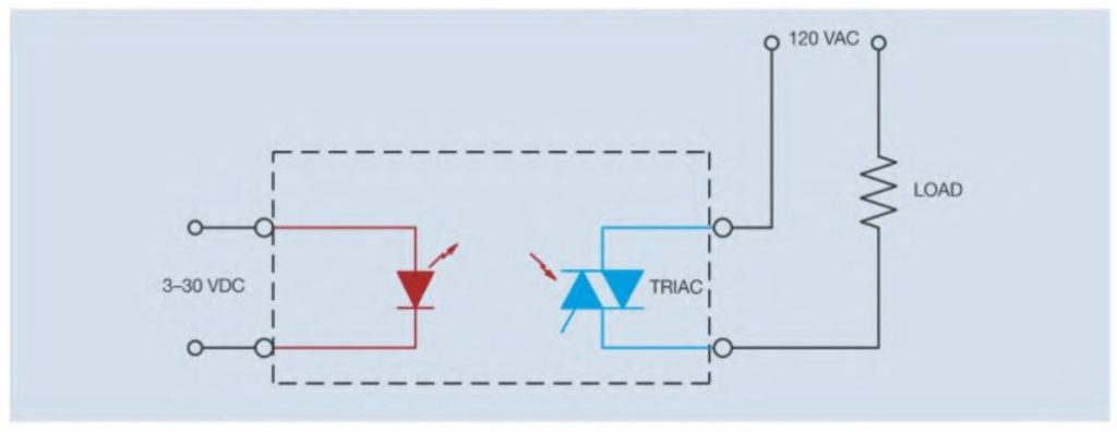
Another type of relay that is found in many applications is the solid-state relay. Solid-state relays employ the use of solid-state devices to connect the load to the line instead of mechanical contacts. Solid-state relays that are intended to connect alternating current loads to the line use a device called a triac. The triac is bidirectional device, which means it permits current to flow through it in either direction. A couple of methods are used to control when the triac turns on or off. One method employs a small relay device that controls the gate of the triac. The relay can be controlled by a low voltage source. When energized, the relay contact closes and supplies power to the gate of the triac, which connects the load to the line. Another common method for controlling the operation of a solid-state relay is called optoisolation, or optical isolation. This method is used by many programmable logic controllers to communicate with the output device. Optoisolation is achieved by using the light from a light-emitting diode (LED) to energize a photo triac. The arrows pointing away from the diode symbol indicate that it emits light when energized. The arrows pointing toward the triac symbol indicate that it must receive light to turn on. Optical isolation is very popular with electronic devices such as computers and programmable logic controllers because there are no moving contacts to wear and the load side of the relay is electrically isolated from the control side. This isolation prevents any electrical noise generated on the load side from being transferred to the control side.
Solid-state relays can also be obtained that control loads connected to direct current circuits.These relays use a transistor to connect the load to the line instead of a triac. Solid-state relays can be obtained in a variety of case styles and ratings. Some have voltage ratings that range from about 3 to 30 volts and can control only a small amount of current, while others can control hundreds of volts and several amperes. The 8 pin IC (integrated circuit) shown in Figure 5-22 contains two solid-state relays that are intended for low power applications. For this solid-state relay to be capable of controlling that amount of power, it must be mounted on a heat sink to increase its ability to dissipate heat. Although this relay is rated 240 volts, it can control devices at a lower voltage also.