Relay Operation
An electromechanical relay (EMR) is a switch that is operated by an electromagnet. It turns a load circuit on or off by energizing an electromagnet, which opens or closes contacts connected in series with a load. A relay consists of two circuits: the coil input or control circuit and the contact output or load circuit. Electromechanical relays are used to control small loads of 15 A or less, such as solenoids, pilot lights, audible alarms, and small motors (1/8 hp or less). In motor circuits, they are often used to control coils in motor contactors and starters.
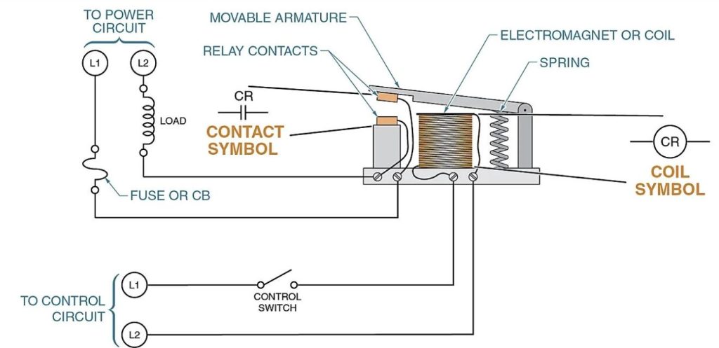
The operation of a relay is similar to that of a contactor. The main difference between a control relay and a contactor is the size and number of contacts. Control relay contacts are relatively small because they need to handle only the small currents used in control circuits. The small size of control relay contacts allows control relays to contain multiple isolated contacts.
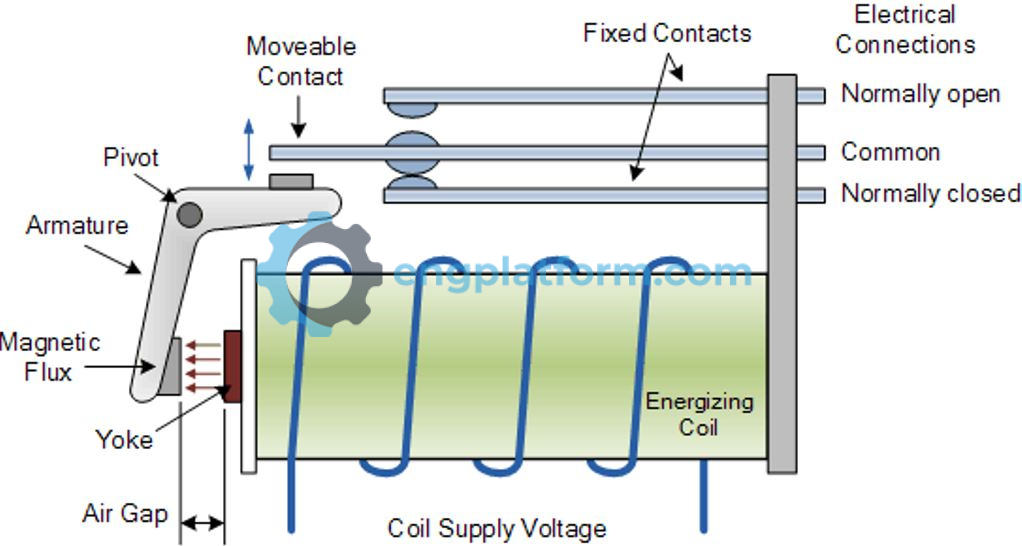
A relay usually has only one coil but may have any number of different contacts. Electromechanical relays contain both stationary and moving contacts. The moving contacts are attached to the armature. Contacts are referred to as normally open (NO) and normally closed (NC). When the coil is energized, it produces an electromagnetic field that causes the armature to move, closing the NO contacts and opening the NC contacts. The plunger moves only about 1/4 inch or less. A letter is used in most diagrams to designate the coil. The letter M frequently indicates a motor starter, while CR is used for control relays. The associated contacts will have the same identifying letters.
Normally open (NO) contacts are open when the coil is de-energized and close when the coil is energized. Normally closed (NC) contacts are closed when the coil is de-energized and open when the coil is energized. Some control relays have a provision for changing contacts from NO to NC types, or vice versa. This can be done with a simple flip-over contact or by removing the contacts and relocating them with spring location changes.
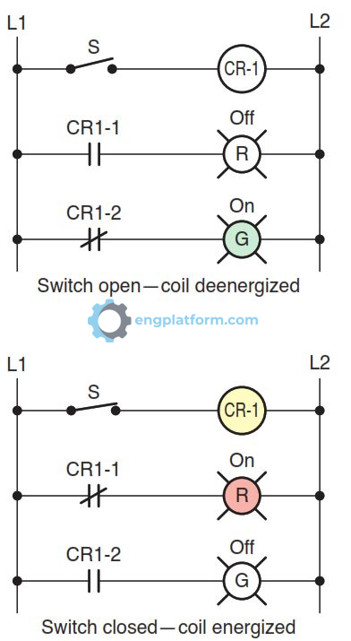
Relays are employed to manage multiple switching operations using a single, independent current. A single relay coil/armature assembly can be utilized to activate multiple contact sets. These contacts can be either normally open, normally closed, or a combination of both. The circuit’s operation can be summarized as follows:
- With the switch open, coil CR1 is deenergized.
- The circuit to the green pilot light is completed through normally closed contact CR1-2, so this light will be on.
- At the same time, the circuit to the red pilot light is opened through normally open contact CR1-1, so this light will be off.
- With the switch closed, the coil is energized.
- The normally open contact CR1-1 closes to switch the red pilot light on.
- At the same time, the normally closed CR1-2 opens to switch the green pilot light off.
Relay Applications
Relays allow us to control high-power devices with low-power signals. The relay coil, which creates a magnetic field, uses very little power, but the contacts that are opened and closed by the magnetic field can handle much more power.
The circuit diagram below demonstrates how a relay can be employed to manage a high-voltage load circuit with a low-voltage control circuit. The relay’s coil is energized by a low-voltage (12 V) source, while the contact interrupts the high-voltage (480 V) circuit. When the switch is closed and opened, the coil is energized and de-energized, respectively. This, in turn, closes and opens the contacts to switch the load on and off.
You can also use a relay to control a high-current load circuit with a low-current control circuit. This is possible because the current that can be handled by the contacts can be much greater than what is required to operate the relay coil. Relay coils are capable of being controlled by low-current signals from integrated circuits and transis-tors, as illustrated in figure below. The operation of the circuit can be summarized as follows:
- The electronic control signal switches the transistor on or off, which in turn causes the relay coil to energize or de-energize.
- The current in the transistor control circuit and relay coil is quite small in comparison to that of the sole-noid load.
- Transistors and integrated circuits (ICs, or chips) must be protected from the brief high-voltage spike produced when the relay coil is switched off.
- In this circuit a diode is connected across the relay coil to provide this protection.
- Note that the diode is connected backward so that it will normally not conduct. Conduction occurs only when the relay coil is switched off; at this moment current tries to continue flowing through the coil and it is harmlessly diverted through the diode.

Relay Styles and Specifications
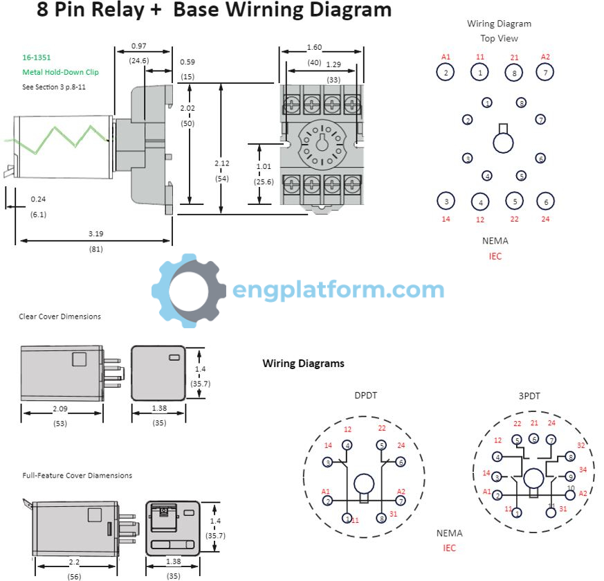
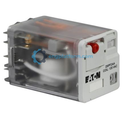
Control relays come in a variety of styles and types. A popular type is the general-purpose ice cube relay. It is named for its size and shape, and the clear plastic enclosure around the contacts. The contacts are not replaceable, but the relay is designed to plug into a socket, making it quick and easy to replace if it fails.
Relay options that aid in troubleshooting are also available. An on/off indicator is installed to indicate the state (energized or deenergized) of the relay coil. A manual override button, mechanically connected to the contact assembly, may be used to move the contacts into their energized position for testing purposes. Use caution when exercising this feature, as the circuit controlling the coil is bypassed and loads may be energized or deenergized without warning.
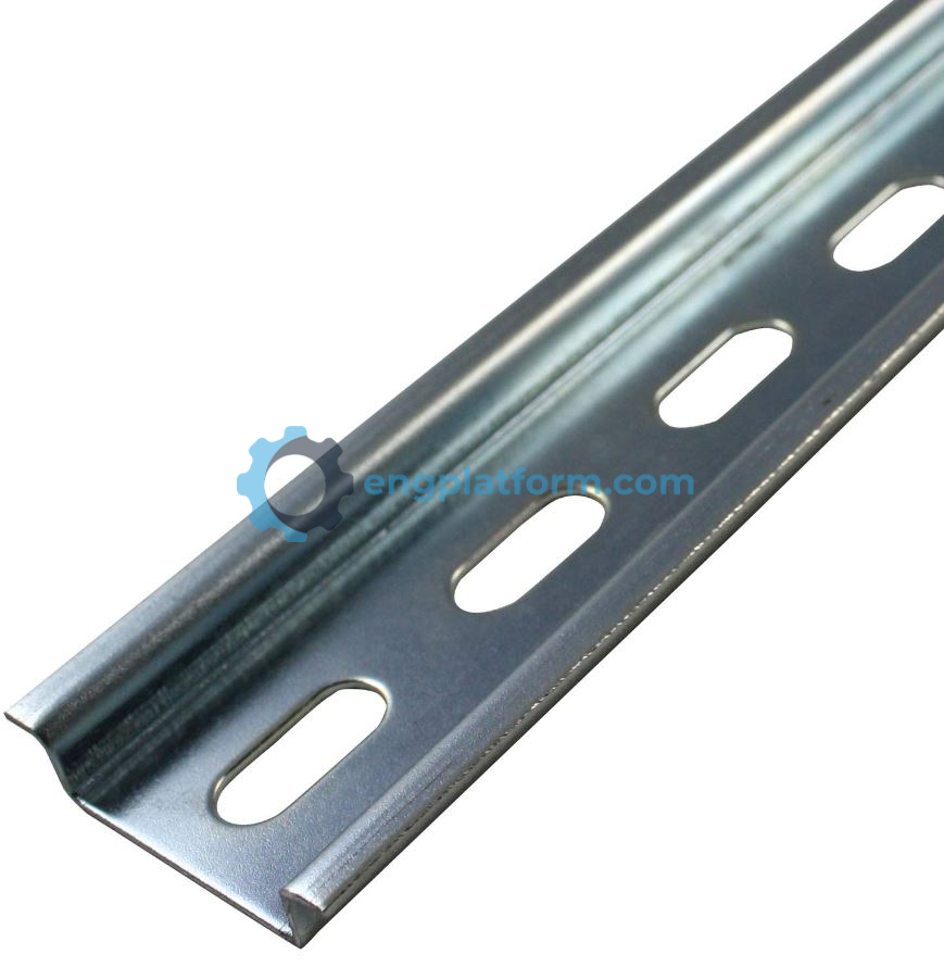
DIN rails are metal rails that are used to mount electrical devices, such as relays, inside control panels. They offer a quick and space-saving solution for common relay control applications. DIN rails are easy to install and remove, making it quick and easy to replace components. They also allow devices to be mounted in a dense configuration, which can save space in control panels. DIN rail mounting systems are widely used in industrial and commercial applications, and they are becoming increasingly popular in residential applications as well.
Like contactors, relay coils and contacts have separate ratings. Relay coils are usually rated for type of operating current (DC or AC), normal operating voltage or current, permissible coil voltage variation (pickup and dropout), resistance, and power. Coil voltages of 12 V DC, 24 V DC, 24 V AC, and 120 V AC are most common. Sensitive relay coils that require as little as 4 mA at 5 V DC are used in relay circuits operated by transistor or integrated circuit chips.
Relays are available in a wide range of switching configurations. Figure 7-9 illustrates common relay contact switching arrangements. Like switch contacts, relay con-tacts are classified by their number of poles, throws, and breaks.
- The number of poles indicates the number of com-pletely isolated circuits that a relay contact can switch. The single-pole contact can conduct current through only one circuit at a time while a double-pole contact can conduct current through two circuits simultaneously.
- A throw is the number of closed contact posi-tions per pole (single or double). The single-throw
contact can control current in only one circuit while the double-throw contact can control two circuits - The term break designates the number of points in a set of contacts where the current will be interrupted during opening of the contacts. All relay contacts are constructed as single break or double break. Single-break contacts have lower current ratings because they break the current at only one point.
In general, relay contact ratings are rated in terms of the maximum amount of current the contacts are capable of handling at a specified voltage level and type (AC or DC). Current ratings specified may include:
- Inrush or make-contact capacity
- Normal or continuous carrying capacity
- Opening or break capacity

Relay contacts are rated for the amount of current and power they can handle. The load-carrying capacity of contacts is typically given as a current value for a resistive load. However, some types of loads, such as lamps and transformers, can cause the inrush current to be much higher than the steady-state value. Therefore, it is important to derate the contacts to a fraction of their resistive load capabilities when used with these types of loads.
For example: it is common to derate contacts to 20% of their resistive load capabilities for lamp loads, and to 50% of their resistive load capabilities for inductive loads, such as transformers.
Relay contacts also have AC and DC ratings, which indicate how much power they can switch. To determine the maximum power capacity of relay contacts, multiply the rated volts by the rated amperes. For example, a 5 A relay rated at 125 V AC can also switch 2.5 A at 250 V AC, and a 5 A relay rated at 24 V DC can switch 2.5 A at 48 V DC, or even 10 A at 12 V DC.