We will discuss the main components of the SOLIDWORKS interface. These main components are the Command Bar, the Task Pane, the Canvas/Graphics Area, and the FeatureManager Design Tree.
When opening a part in SOLIDWORKS, regardless of whether it is new or existing, you will be faced with the view shown in the following screenshot. We will cover the four main categories of this screen: the Command Bar, the FeatureManager Design Tree, the Task Pane, and the Canvas/Graphics Area.
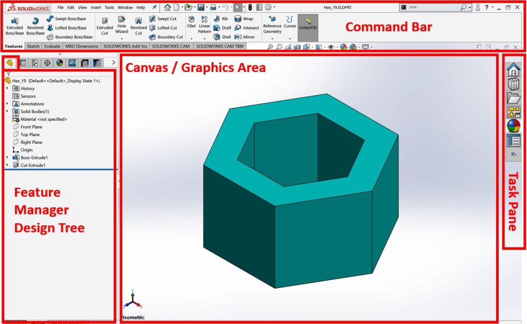
We will look at the Command Bar, the FeatureManager Design Tree, the Canvas/Graphics Area, and the Task Pane
The Command Bar
The Command Bar is located at the top of the screen. It contains all the SOLIDWORKS commands that are used for building models. It contains different categories of commands, and each category contains a set of different commands.
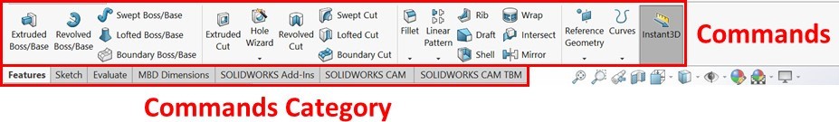
Different categories (tabs) of commands correspond to different functions. For example, in the Sketch category/tab, you will find all the commands that we will need in the sketching phase. In the Features category/tab, you will find all the commands that we will need in order to go from the sketching phase and start creating a 3D model. The categories that are shown in the preceding screenshot are not the only ones SOLIDWORKS provides, but they are the most common ones we will use. To show the hidden Commands categories, we can do the following:
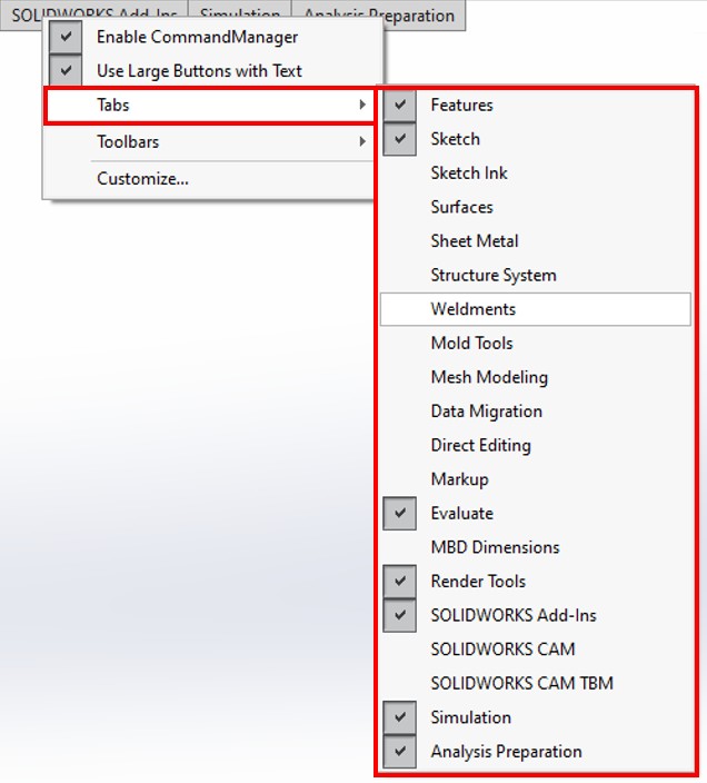
- Right-click on any of the Commands categories, and then expand the Tabs menu. Which contains more Commands categories, such as Surfaces, Weldments, and Mold Tools
- Select the categories you want to be shown. By doing this, these categories will be added to the Command Bar
This concludes our overview of the Command Bar, which contains the different commands we will use as we build 3D models. Now, we will look at the FeatureManager Design Tree.
The Feature Manager Design Tree
The FeatureManager Design Tree details everything that goes into creating your parts. The following screenshot shows the FeatureManager Design Tree for the part we explored in this chapter. We can simplify the FeatureManager Design Tree by splitting it into four parts
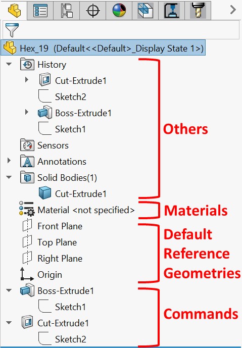
The four parts of the FeatureManager Design Tree are listed here:
- Commands/Features: These are the commands that are used to build the model. This includes sketches, features, and any other supporting commands that were added during the modeling phase (since we are building a 3D model). In the preceding screenshot, two features were used to create the model, as indicated by Commands. The first is Boss-Extrude1 and the second is Cut-Extrude1. Note that these commands are listed in the order of when they were applied.
- Default Reference Geometries: The SOLIDWORKS canvas can be understood as endless space. These Default Reference Geometries are what can fix our model to a specific point or plane. Without these, our model will be floating in an endless space without any fixtures. Throughout this book, we will start our models from these default references. There are three planes (Front Plane, Right Plane, and Top Plane), in addition to the origin.
- Materials: Realistically, all of the artifacts we have around us are made of a certain material. Some examples of materials include plastic, iron, steel, and rubber. SOLIDWORKS allows us to assign which structural material the part will be made of
The design tree helps us to easily identify how the model was built and in which sequence. This makes it easier for us to modify existing models. Now, let’s look at the canvas.
The Canvas/Graphics Area
The canvas provides a visual representation of the model we have at hand. It contains three main components
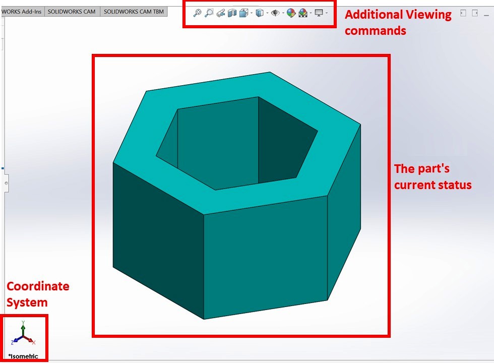
Let’s break down the components, as follows:
- Coordinate System: This shows the orientation of the model in relation to the default coordinate system in terms of the x, y, and z axes. They are interactive and can be used to position the viewing angle of the model. By clicking on the various axes, you can arrive at that viewing orientation.
- The part’s current status: This shows the current status of the part at work. This is updated with every construction command that’s used to build the model.
- Additional viewing commands: These provide alternative views of the model, such as the wireframe view and section view. It also provides shortcuts that we can use to modify the scene, the appearance of the model, and hide/show various properties
When controlling the model in the canvas, using a mouse with a scroll wheel is recommended due to the functionalities the scroll wheel has. Here are two ways the scroll helps model control:
- When the cursor is within the canvas, rolling the scroll wheel will allow us to zoom in and out of the cursor’s location.
- When the cursor is within the canvas, pressing on the scroll wheel and moving the mouse will rotate the model in a certain direction. For example, if we move the mouse to the right, the model will pivot to the right.
The Task Pane
The Task Pane shows to the right of our interface by default. It contains shortcuts for the different tools we will be using in order to enhance the efficiency of our work. This includes access to common online resources and forums, as well as different tools, such as appearance adjustments and the View Palette (mainly for drawing files)