Manual Starter
Manual motor starters are a very basic way to supply power to a motor. A manual control circuit is a circuit that requires the operator to control the motor directly at the location of the starter. Figure 2-45 shows an example of a three-phase manual-start motor control circuit. The dot-ted line across the contacts designates a manual starter (as opposed to a magnetic starter). Incoming power supply wires (L1, L2, and L3) connect to the top of the contacts, and the opposite sides of the contacts are connected to the overload heater elements. The motor terminal connec-tions (T1, T2, and T3) connect to the 3ϕ motor.
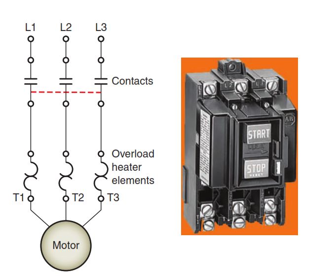
Manual starters are operated by the manual start/stop mechanism located on the front of the starter enclosure
The start/stop mechanism moves all three contacts at once to close (start) or open (stop) the circuit to the motor. The National Electrical Code requires that a starter not only turn a motor on and off but also protect it from overloads. The three thermal overload protective devices are installed to mechanically trip open the starter contacts when an overload condition is sensed. Manual three-phase start-ers are used in low horsepower applications such as drill presses and table saws where remote pushbutton control is not required.
Magnetic Starter
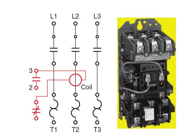
Magnetic motor starters allow a motor to be controlled from any location. Figure 2-46 shows a typical three-phase across-the-line (full-voltage) magnetic starter. The line terminals, load terminals, motor starter coil, overload relays, and auxiliary holding contact are shown. When the starter coil is energized, the three main contacts as well as the holding contact close. Should an overload condi-tion occur, the normally closed OL relay contact would open. In addition to the power circuit, the manufacturer provides some control circuit wiring. In this case the prewired control circuit wiring consists of two connec-tions to the starter coil. One side of the starter coil is fac-tory wired to the overload relay contact and the other side to the holding contact.
Magnetic motor control circuits are divided into two basic types: the two-wire control circuit, and the three-wire control circuit. Two-wire control circuits are designed to start or stop a motor when a remote control device such as a thermostat or pressure switch is activated or deactivated. Figure 2-47 shows a typical two-wire control circuit. The operation of the circuit can be summarized as follows:
- The circuit has only two wires leading from the control device to the magnetic starter.
- The starter operates automatically in response to the state of the control device (pressure switch) without the assistance of an operator.
- When the contacts of the pressure switch close, power is supplied to the starter coil, causing it to energize.
- As a result, the motor is connected to the line through the power contacts.
- The starter coil is deenergized when the contacts of the pressure switch open, switching the motor off.

The two-wire control systems provide low-voltage release but not low-voltage protection. They use a main-tained rather than a momentary-contact type of control device. If the motor is stopped by a power interruption, the starter deenergizes (low-voltage release), but also reenergizes if the control device remains closed when the circuit has power restored. Low-voltage protection is not provided, as there is no way for the operator to be automatically protected from the circuit once power has been restored. Two-wire control circuits are used to auto-matically operate machinery where the automatic restart-ing characteristic is desirable and there is no danger of persons being injured if the equipment should suddenly restart after a power failure. Sump pumps and refrigera-tor compressor controls are two common applications for two-wire control systems.
Three-wire control provides low-voltage protection. The starter will drop out when there is a voltage failure, but it will not pick up automatically when voltage returns. Three-wire control uses a momentary-contact control device and a holding circuit to provide the power failure protection. Figure 2-48 shows a typical three-wire control circuit. The operation of the circuit can be summarized as follows:
- Three-wires are run from the start/stop pushbutton station to the starter.
- The circuit uses a normally closed (NC) stop push button wired in series with the parallel combination consisting of normally open (NO) start push button and normally open holding contact (M).
- When the momentary-contact start button is closed, line voltage is applied to the starter coil to energize it.
- The three main M contacts close to apply voltage to the motor.
- The auxiliary M contact closes to establish a circuit around the start button.
- When the start button is released, the starter coil remains energized by the closed M auxiliary con-tact (also known as the holding, seal-in, or memory contact) and the motor will continue to operate.
- When the momentary-contact stop button is opened, all voltage to the starter coil is lost. The main con-tacts are opened along with the holding contact and the motor stops.
- The starter drops out at low or no voltage and can-not be reenergized unless line voltage returns and the start button is closed.

Basically, three-wire control uses a maintaining circuit consisting of a holding contact wired in parallel with a start button. When the starter drops out, the holding contact opens and breaks the circuit to the coil until the start button is pressed to restart the motor. In the event of a power failure, the maintaining circuit is designed to pro-tect against automatic restarting when the power returns. This type of protection must be used where accidents or damage might result from unexpected starts. All devices that start the circuit are connected in parallel while those that stop the circuit are connected in series.