Limit Switches
Mechanically operated switches are controlled by physical factors such as pressure, position, and temperature. They are often used in motor control circuits to automatically start, stop, or reverse motors. Limit switches are a common type of mechanically operated switch. They are designed to operate only when a predetermined limit is reached, such as when an object comes into contact with the switch’s actuator. Limit switches are used in a wide variety of applications, such as industrial automation systems, machine tools, and conveyor belts. In other words, mechanically operated switches are like automatic on/off switches that are triggered by physical changes in their environment. Limit switches are a specific type of mechanically operated switch that are used to control motors.
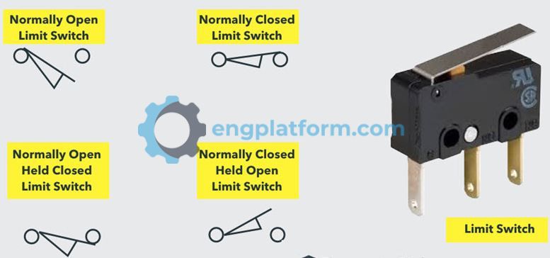
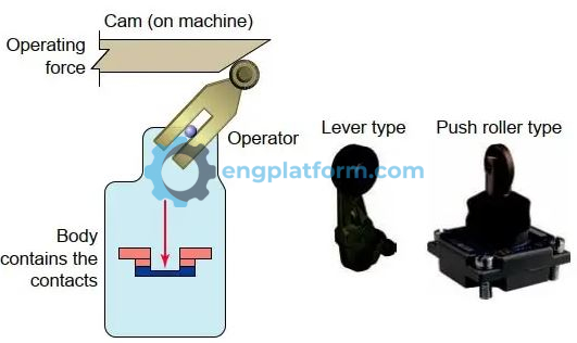
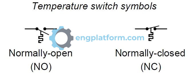
Limit switches are made up of two main parts: the body and the operator head (also called the actuator). The body houses the electrical contacts that open or close in response to the movement of the actuator. Limit switches can have different types of contacts, including normally open (NO), normally closed (NC), momentary (spring-returned), and maintained-contact types.
- Normally open (NO) contacts are open by default and close when the actuator is moved.
- Normally closed (NC) contacts are closed by default and open when the actuator is moved.
- Momentary (spring-returned) contacts close when the actuator is moved and return to their open state when the actuator is released.
- Maintained-contact contacts close when the actuator is moved and remain closed until they are manually reset.
The most common configuration for a limit switch is one NO and one NC contact block. This allows the switch to be used to control both starting and stopping a motor. If a limit switch has two or more sets of contacts that are electrically isolated, the loads that these contacts are controlling must be wired on the same side of the line. This is to prevent a short circuit from occurring.
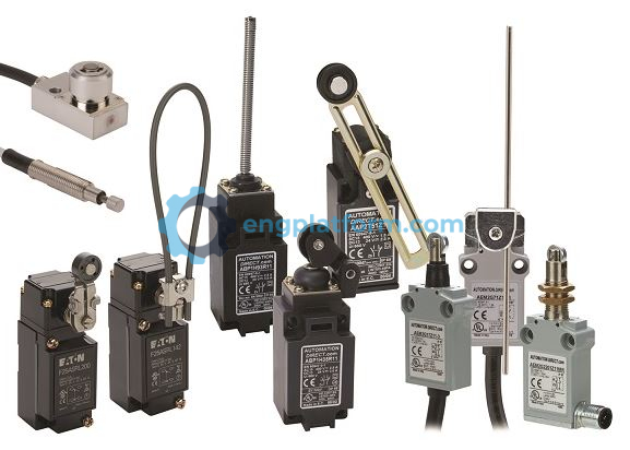
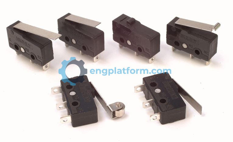
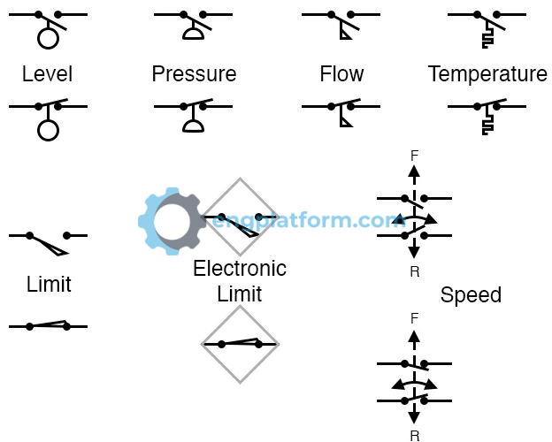
Limit switches come with a wide variety of operators designed for a broad range of applications. These include:
- Lever type, which consists of a single arm with a roller attached at the end to help prevent wear. The length of the lever may be fixed or adjustable. Adjustable types are used in applications that require adjustment of the actuator length or travel.
- Fork lever, which is designed for applications where the actuating object travels in two directions. A typical application is a machine bed that automatically alternates back and forth.
- Wobble stick, which is used in applications that require detection of a moving object from any direction rather than in one or two directions along a single plane. They may be constructed of steel, plastic, Teflon, or nylon and are connected to the limit switch by a flexible spring attachment.
- Push roller type, which operates by a direct forward movement into the limit switch. This type has the least amount of travel compared to other types and is commonly used to prevent overtravel of a machine part or object. The limit switch contacts are connected so as to stop the forward movement of the object when it makes contact with it
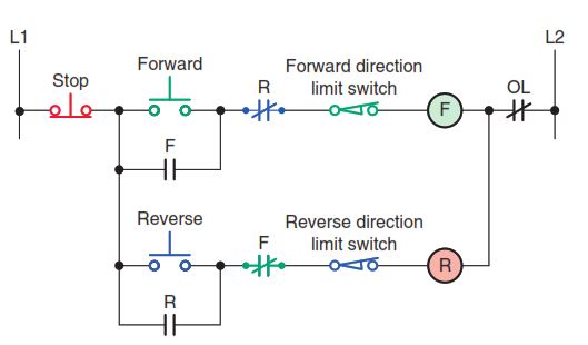
A common application for limit switches is to limit the travel of electrically operated doors, conveyors, hoists, machine tool worktables, and similar devices. Figure below shows the control circuit for starting and stopping a motor A common application for limit switches is to limit the travel of electrically operated doors, conveyors, hoists, machine tool worktables, and similar devices:
- Pressing the momentary forward push button completes the circuit for the F coil, closing the normally open maintaining contact and sealing in the circuit for the forward starter coil.
- At the same instant, the normally closed interlock contact F opens to prevent the reverse direction of the motor.
- To reverse the motor direction, the operator must first press the stop button to de-energize the F coil and then press the reverse push button.
- If overtravel position should be reached in either the forward or reverse direction, the respective NC limit switch will open to prevent any further travel in that direction.
- The forward direction is also interlocked with a normally closed R contact.
The micro limit switch is a snap-action switch housed in a small enclosure. Snap action switches are mechanical switches that produce a very rapid transfer of contacts from one position to another. They are useful in situations that require a fast opening or closing of a circuit. In a snap-action switch, the actual switching of the circuit takes place at a fixed speed no matter how quickly or slowly the activating mechanism moves.
Micro limit switches are a type of limit switch that use a single-pole, double-throw (SPDT) contact arrangement. This means that the switch has three terminals: common, normally open (NO), and normally closed (NC). The common terminal is connected to one of the other two terminals depending on the position of the actuator.
Micro limit switches are typically made of molded plastic, which offers less electrical isolation and physical protection than traditional limit switches. For this reason, micro limit switches are usually mounted inside enclosures to protect them from damage.
When used in conjunction with equipment doors, micro limit switches can function as safety devices. They can be interlocked with the control circuitry to prevent the process from operating if the door is not closed.
Here are some of the key differences between traditional limit switches and micro limit switches:
- Electrical configuration: Traditional limit switches typically have two electrically isolated contacts, while micro limit switches use a single-pole, double-throw contact arrangement.
- Construction: Traditional limit switches are often made of metal or other durable materials, while micro limit switches are typically made of molded plastic.
- Protection: Traditional limit switches offer better electrical isolation and physical protection than micro limit switches. This makes them suitable for use in harsh environments.
- Applications: Traditional limit switches are often used in industrial and commercial applications where durability and protection are important. Micro limit switches are often used in applications where electrical isolation and physical protection are less critical, such as in consumer electronics and appliances.
Temperature Control Devices
Temperature control devices (also called thermostats, depending on the application) monitor the temperature or changes in temperature for a particular process. Although there are many types available, they are all actuated by some specific environmental temperature change. Temperature switches open or close when a designated temperature is reached. Temperature control devices are used in heating or cooling applications where temperature must be maintained within preset limits.
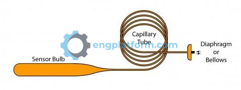
Temperature switches are designed to work with a number of different operating principles. These devices typically comprise sensing elements and switching contacts housed in a single mechanical assembly. Switches may open or close on temperature rise, depending on their internal construction. The capillary tube temperature switch operates on the principle that a temperature-sensitive liquid will expand and contract with a change in temperature.
- Pressure in the system changes in proportion to tem-perature and is transmitted to the bellows through a bulb and capillary tube.
- As the temperature rises, the pressure in the tube increases.
- Similarly, as the temperature decreases, the pressure in the tube decreases.
- Bellows motion, in turn, is transmitted through a mechanical linkage to actuate a precision switch at a predetermined setting.
- Capillary tube–type temperature switches can be connected to a remote fluid-containing bulb, allowing the switch element to be remote from the sensing bulb and environment or process under control.
Temperature switches rated to carry motor current may be used with fractional-horsepower manual starters. Note that a double-pole manual starter is used. This type of starter is required when both line leads to the motor must be switched, such as for a 230 V, single-phase source. When the three-position selector switch is in the auto position, the temperature switch reacts to a preset rising temperature to automatically switch the motor on. When the temperature drops below the preset value, the contacts open to turn the motor off.
Pressure Switches
Pressure switches are used to monitor and control the pressure of liquids and gases. They are commonly used to monitor a system and, in the event that pressure reaches a dangerous level, open relief valves or shut the system down. The three categories of pressure switches used to activate electrical contacts are positive pressure, vacuum (negative pressure), and differential pressure.
Pressure switches are used in many different types of industries and applications. They can be used to control pneumatic systems, maintaining preset pressures between two values. The operation of the circuit can be summarized as follows:
- The pressure switch is used to stop the motor when tank pressure reaches a preset limit. The differential between the high and low cutout settings is known as the span or dead band.
- When the preset system pressure is reached, the NC contacts of the pressure switch open to de-energize the motor starter coil and automatically switch the compressor motor off.
- To prevent frequent stopping and starting of the motor, this type of pressure switch has a built-in pressure differential between the set stopping and starting pressures. This differential is referred to as the dead band.
Float and Flow Switches
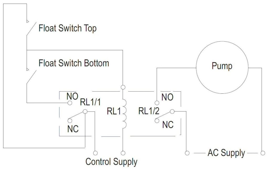
A float switch (also called a level switch) is used to sense the height of a liquid. Float switches provide automatic control for motors that pump liquid from a sump or into a tank. The switch must be installed above the tank or sump, and the float must be in the liquid for the float switch to operate. For tank operation, a float operator assembly is attached to the float switch by a rod, chain, or cable. The float switch is actuated according to the location of the float in the liquid.
There are several styles of float switches. One type uses a rod that has a float mounted on one end. In this application, a float switch is used to control the pump motor in an automatic tank-filling operation. The operation of the circuit can be summarized as follows:
- The float switch contacts are open when the float forces the operating lever to the up position.
- As the liquid level falls, the float and rod move downward.
- When the float reaches a preset low level, the float switch contacts close, activating the circuit and starting the pump motor to refill the tank.
- Adjustable stops on the rod determine the amount of movement that must take place before the switch contacts open or close.
A flow switch is used to detect the movement of air or liquid through a duct or pipe. In certain applications, it is essential to be able to determine whether fluid is flowing in a pipeline, duct, or other conduit and to respond accordingly to such a determination. The paddle extends into the pipe and moves to close the electrical contacts of the flow switch when the fluid flow is sufficient to overcome the spring tension on the paddle. When the flow stops, the contacts open. On most paddle-type flow switches the spring tension is adjustable, allowing for different flow rate adjustments.