Different types of electrical drawings are used in working with motors and their control circuits. In order to facilitate making and reading. To read electrical motor drawings, it is necessary to know both the meaning of the symbols and how the equipment operates
Motor Symbols
A motor control circuit can be defined as a means of supplying power to and removing power from a motor. The symbols used to represent the different components of a motor control system can be considered a type of technical shorthand. The use of these symbols tends to make circuit diagrams less complicated and easier to read and understand. In motor control systems, symbols and related lines show how the parts of a circuit are connected to one another. Unfortunately, not all electrical and electronic symbols are standardized. You will find slightly different symbols used by different manufacturers. Also, symbols sometimes look nothing like the real thing, so you have to learn what the symbols mean.

Abbreviations for Motor Terms
An abbreviation is the shortened form of a word or phase. Uppercase letters are used for most abbreviations. The following is a list of some of the abbreviations commonly used in motor circuit diagrams.
- AC alternating current
- ARM armature
- AUTO automatic
- BKR breaker
- COM common
- CR control relay
- CT current transformer
- DC direct current
- DB dynamic braking
- FLD field
- FWD forward
- GND ground
- HP horsepower
- L1, L2, L3 power line connections
- LS limit switch
- MAN manual
- MTR motor
- M motor starter
- NEG negative
- NC normally closed
- NO normally open
- OL overload relay
- PH phase
- PL pilot light
- POS positive
- PWR power
- PRI primary
- PB push button
- REC rectifier
- REV reverse
- RH rheostat
- SSW safety switch
- SEC secondary
- 1PH single-phase
- SOL solenoid
- SW switch
- T1, T2, T3 motor terminal connections
- 3PH three-phase
- TD time delay
- TRANS transformer
Motor Ladder Diagrams
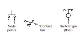
Motor control drawings provide information on circuit operation, device and equipment location, and wiring instructions. Symbols used to represent switches consist of node points (places where circuit devices attach to each other), contact bars, and the specific symbol that identifies that particular type of switch. Although a control device may have more than one set of contacts, only the contacts used in the circuit are represented on control drawings.
A variety of control diagrams and drawings are used to install, maintain, and troubleshoot motor control systems. These include ladder diagrams, wiring diagrams, line diagrams, and block diagrams. A “ladder diagram” (considered by some as a form of a schematic diagram) focuses on the electrical operation of a circuit, not the physical location of a device. For example, two stop push buttons may be physically at opposite ends of a long conveyor, but electrically side by side in the ladder diagram.
Ladder diagrams are drawn with two vertical lines and any number of horizontal lines.
- The vertical lines (called rails) connect to the power source and are identified as line 1 (L1) and line 2 (L2).
- The horizontal lines (called rungs) are connected across L1 and L2 and contain the control circuitry.
- Ladder diagrams are designed to be read like a book, starting at the top left and reading from left to right and top to bottom.

Because ladder diagrams are easier to read, they are often used in tracing through the operation of a circuit. Most programmable logic controllers (PLCs) use the ladder-diagramming concept as the basis for their programming language.
Some motor ladder diagrams illustrate only the single-phase control circuit connected to L1 and L2, and not the three-phase power circuit supplying the motor. Figure 2-4 shows both the power circuit and control circuit wiring.
- On diagrams that include power and control circuit wiring, you may see both heavy and light conductor lines. The heavy lines are used for the higher-current power circuit and the lighter lines for the lower-current control circuit.
- Conductors that cross each other but make no electrical contact are represented by intersecting lines with no dot.
- Conductors that make contact are represented by a dot at the junction.
- In most instances, the control voltage is obtained directly from the power circuit or from a step-down control transformer connected to the power circuit. Using a transformer allows a lower voltage (120 V AC) for the control circuit while supplying the three-phase motor power circuit with a higher voltage (480 V AC) for more efficient motor operation

A ladder diagram gives the necessary information for easily following the sequence of operation of the circuit. It is a great aid in troubleshooting as it shows, in a simple way, the effect that opening or closing various contacts has on other devices in the circuit. All switches and relay contacts are classified as normally open (NO) or normally closed (NC). The positions drawn on diagrams are the electrical characteristics of each device as would be found when it is purchased and not connected in any circuit. This is sometimes referred to as the “off-the-shelf ” or deenergized state. It is important to understand this because it may also represent the deenergized position in a circuit. The deenergized position refers to the component position when the circuit is deenergized, or no power is present on the circuit. This point of reference is often used as the starting point in the analysis of the operation of the circuit.
A common method used to identify the relay coil and the contacts operated by it is to place a letter or letters in the circle that represents the coil. Each contact that is operated by this coil will have the coil letter or letters written next to the symbol for the contact. Sometimes, when there are several contacts operated by one coil, a number is added to the letter to indicate the contact number ‘‘separated by dash” or other text to be consistent. Although there are standard meanings of these letters, most diagrams provide a key list to show what the letters mean; generally they are taken from the name of the device.

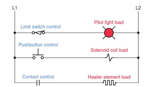
A load is a circuit component that has resistance and consumes electric power supplied from L1 to L2, as illustrated in Figure 2-6. Control coils, solenoids, horns, and pilot lights are examples of loads. At least one load device must be included in each rung of the ladder diagram. Without a load device, the control devices would be switching an open circuit to a short circuit between L1 and L2. Contacts from control devices such as switches, push buttons, and relays are considered to have little or no resistance in the closed state. Connection of contacts in parallel with a load also can result in a short circuit when the contact closes. The circuit current will take the path of least resistance through the closed contact, shorting out the energized load.
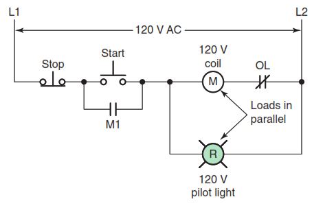
Normally loads are placed on the right side of the ladder diagram next to L2 and contacts on the left side next to L1. One exception to this rule is the placement of the normally closed contacts controlled by the motor overload protection device. These contacts are drawn on the right side of the motor starter coil as shown in Figure 2-7. When two or more loads are required to be energized simultaneously, they must be connected in parallel. This will ensure that the full line voltage from L1 and L2 will appear across each load. If the loads are connected in series, neither will receive the entire line voltage necessary for proper operation. Recall that in a series connection of loads, the applied voltage is divided between each of the loads. In a parallel connection of loads, the voltage across each load is the same and is equal in value to the applied voltage.
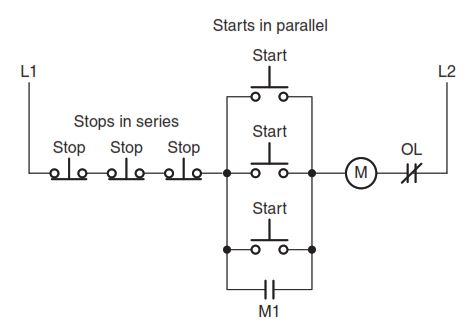
Control devices such as switches, push buttons, limit switches, and pressure switches operate loads. Devices that start a load are usually connected in parallel, while devices that stop a load are connected in series. For example, multiple start push buttons controlling the same motor starter coil would be connected in parallel, while multiple stop push buttons would be connected in series (Figure 2-8). All control devices are identified with the appropriate nomenclature for the device (e.g., stop, start). Similarly, all loads are required to have abbreviations to indicate the type of load (e.g., M for starter coil). Often an additional numerical suffix is used to differentiate multiple devices of the same type. For example, a control circuit with two motor starters might identify the coils as M1 (contacts 1-M1, 2-M1, etc.) and M2 (contacts 1-M2, 2-M2, etc.), as illustrated in Figure 2-9.

same type.
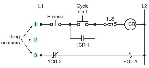
As the complexity of a control circuit increases, its ladder diagram increases in size, making it more difficult to read and locate which contacts are controlled by which coil. “Rung numbering” is used to assist in reading and understanding larger ladder diagrams. Each rung of the ladder diagram is marked (rung 1, 2, 3, etc.), starting with the top rung and reading down. A rung can be defined as a complete path from L1 to L2 that contains a load. Figure 2-10 illustrates the marking of each rung in a line diagram with three separate rungs:
- The path for rung 1 is completed through the reverse push button, cycle start push button, limit switch 1LS, and coil 1CR.
- The path for rung 2 is completed through the reverse push button, relay contact 1CR-1, limit switch 1LS, and coil 1CR. Note that rung 1 and rung 2 are identified as two separate rungs even though they control the same load. The reason for this is that either the cycle start push button or the 1CR-1 relay contact completes the path from L1 to L2.
- The path for rung 3 is completed through relay contact 1CR-2 and solenoid SOL A.
“Numerical cross-referencing” is used in conjunction with the rung numbering to locate auxiliary contacts controlled by coils in the control circuit. At times auxiliary contacts are not in close proximity on the ladder diagram to the coil controlling their operation. To locate these contacts, rung numbers are listed to the right of L2 in parentheses on the rung of the coil controlling their operation. In the example shown in Figure 2-11:
- The contacts of coil 1CR appear at two different locations in the line diagram.
- The numbers in parentheses to the right of the line diagram identify the line location and type of contacts controlled by the coil.
- Numbers appearing in the parentheses for normally open contacts have no special markings.
- Numbers used for normally closed contacts are identified by underlining or overscoring the number to distinguish them from normally open contacts.
- In this circuit, control relay coil 1CR controls two sets of contacts: 1CR-1 and 1CR-2. This is shown by the numerical code 2, 3.

Some type of “wire identification” is required to correctly connect the control circuit conductors to their components in the circuit. The method used for wire identification varies for each manufacturer. Figure 2-12 illustrates one method where each common point in the circuit is assigned a reference number:
- Numbering starts with all wires that are connected to the L1 side of the power supply identified with the number 1.
- Continuing at the top left of the diagram with rung 1, a new number is designated sequentially for each wire that crosses a component.
- Wires that are electrically common are marked with the same numbers.
- Once the first wire directly connected to L2 has been designated (in this case 5), all other wires directly connected to L2 will be marked with the same number.
- The number of components in the first line of the ladder diagram determines the wire number for conductors directly connected to L2.
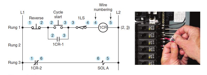
Figure 2-13 illustrates an alternative method of assigning wire numbers. With this method all wires directly connected to L1 are designated 1 while all those connected to L2 are designated 2. After all the wires with 1 and 2 are marked, the remaining numbers are assigned in a sequential order starting at the top left of the diagram. This method has as its advantage the fact that all wires directly connected to L2 are always designated as 2. Ladder diagrams may also contain a series of descriptions located to the right of L2, which are used to document the function of the circuit controlled by the output device.

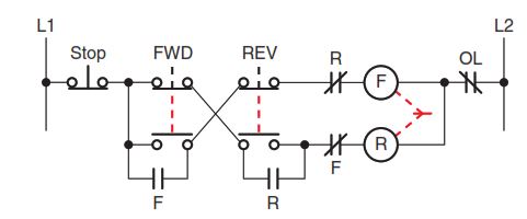
A broken line normally indicates a mechanical con- nection. Do not make the mistake of reading a broken line as a part of the electrical circuit. In Figure 2-14, the vertical broken lines on the forward and reverse push buttons indicate that their normally closed and normally open contacts are mechanically connected. Thus, pressing the button will open the one set of contacts and close the other. The broken line between the F and R coils indicates that the two are mechanically interlocked. Therefore, coils F and R cannot close contacts simultaneously because of the mechanical interlocking action of the device.
When a control transformer is required to have one of its secondary lines grounded, the ground connection must be made so that an accidental ground in the control circuit will not start the motor or make the stop button or control inoperative. Figure 2-15a illustrates the secondary of a control transformer properly grounded to the L2 side of the circuit. When the circuit is operational, the entire circuit to the left of coil M is the ungrounded circuit (it is the “hot” leg). A fault path to ground in the ungrounded circuit will create a short-circuit condition causing the control transformer fuse to open.
Figure 2-15b shows the same circuit improperly grounded at L1. In this case, a short to ground to the left of coil M would energize the coil, starting the motor unexpectedly. The fuse would not operate to open the circuit and pressing the stop button would not de-energize the M coil. Equipment damage and personnel injuries would be very likely. Clearly, output devices (loads) must be directly connected to the grounded side of the circuit.