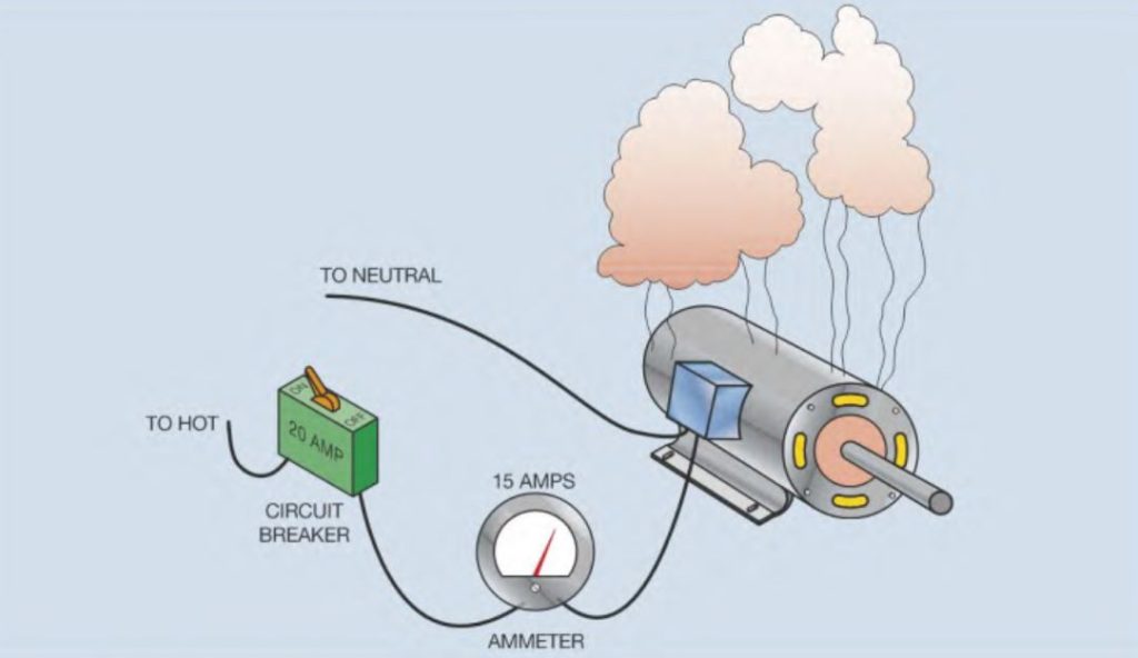
Overloads should not be confused with fuses or circuit breakers. Fuses and circuit breakers are designed to protect the circuit from a direct ground or short-circuit condition. Overloads are designed to protect the motor from an overload condition. Assume, for example, that a motor has a full load current rating of 10 amperes. Also assume that the motor is connected to a circuit that is protected by a 20 ampere circuit breaker. Now assume that the motor becomes overloaded and has a current draw of 15 amperes. The motor is drawing 150 percent of full load current. This much of an overload will overheat the motor and damage the windings. Because the current is only 15 amperes, the 20 ampere circuit breaker will not open the circuit to protect the motor. Overload relays are designed to open the circuit when the current becomes 115 percent to 125 percent of the motor full load current. The setting of the overload depends on the properties of the motor that is to be protected.
Overload Properties
All overload relays must possess certain properties in order to protect a motor.
- They must have some means of sensing motor current. Some overload relays do this by converting motor current into a proportionate amount of heat and oth- ers sense motor current by the strength of a magnetic field.
- They must have some type of time delay. Motors typically have a current draw of 300 percent to 800 percent of motor full load current when they start. Motor starting current is referred to as locked rotor current. Because overload relays are generally set to trip at 115 percent to 125 percent of full load motor current, the motor could never start if the overload relay tripped instantaneously.
- Overload relays are divided into two separate sections: the current sensing section and the contact section. The current sensing section is connected in series with the motor and senses the amount of motor current. This section is typically connected to voltages that range from 120 volts to 600 volts. The contact section is part of the control circuit and operates at the control circuit voltage. Control circuit voltages generally range from 24 volts to 120 volts.
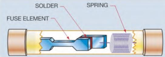
Dual Element Fuses
Some fuses are intended to provide both short circuit protection and overload protection. These fuses are called dual element time delay fuses. The fuse link is designed to open quickly under a large amount of excessive current. This link protects the circuit against direct grounds and short circuits. The second contains a solder link that is connected to a spring. The solder is a highly controlled alloy designed to melt at a particular temperature. If motor current becomes excessive, the solder melts and the spring pulls the link apart. The necessary time delay is achieved because of the time it takes for the solder to melt, even under a large amount of current. If motor current returns to normal after starting, the solder will not get hot enough to melt.