An electric motor is a device that converts electrical energy into mechanical energy by utilizing interacting magnetic fields1. Electric motors are employed in a wide range of applications, including residential, commercial, and industrial operations. This chapter focuses on the operating principles of various types of electric motors, such as DC, universal, and AC motors.
Magnetism
Electric motors are one of the most important inventions in human history. They convert electrical energy into mechanical energy, and they are used in a wide variety of applications, from powering our homes and businesses to transportation and manufacturing.
There are two main types of electric motors: AC and DC. AC motors use alternating current, while DC motors use direct current. Both types of motors use magnetism to operate.
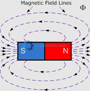
A permanent magnet has a magnetic field around it. The lines of flux in a magnetic field represent the direction and strength of the magnetic field. The more lines of flux, the stronger the magnetic field.
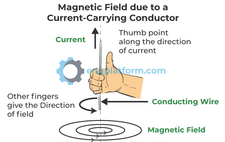
When an electric current flows through a wire, it creates a magnetic field around the wire. The direction of the magnetic field depends on the direction of the current flow.
An electric motor uses two magnetic fields to create rotation. One magnetic field is created by a permanent magnet, and the other magnetic field is created by an electric current flowing through a coil of wire.
When the two magnetic fields interact, they cause the coil of wire to rotate. The rotation of the coil of wire is transferred to the shaft of the motor, which causes the motor to spin.
Electric motors are used in a wide variety of applications because they are efficient, reliable, and versatile. They can be used to power a wide range of devices, from small appliances to large industrial machinery.
Electromagnetism
A current-carrying conductor produces a magnetic field that takes the form of concentric circles around the wire. The strength of the magnetic field is directly proportional to the amount of current flowing through the conductor. The direction of the magnetic field created is related to the direction of current flow through a conductor. This relationship is known as the left-hand conductor rule. The left-hand conductor rule uses electron flow from negative to positive as the basis for the current direction. When you place your left hand so that your thumb points in the direction of the electron flow, your curled fingers point in the direction of the lines of flux that circle the conductor.
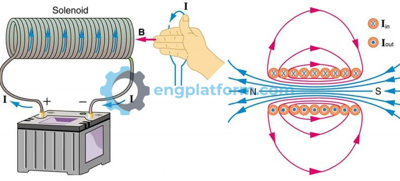
When a current-carrying conductor is shaped into a coil, it creates a stronger magnetic field than the individual magnetic fields created by each turn of the wire. This is because the magnetic fields of the individual turns of wire add together. The magnetic field of a wire coil is also stronger when it has an iron core. This is because the iron core provides a path for the magnetic lines of force that is easier to follow than air. The polarity of the poles of a coil reverses whenever the current flow through the coil reverses. This is because the direction of the magnetic field depends on the direction of the current flow. The reversibility of the polarity of a coil is essential for the operation of electric motors. In an electric motor, the current flowing through the stator coils is reversed periodically. This causes the polarity of the stator magnetic field to reverse periodically. The rotor of the motor is attracted to the stator magnetic field, so the rotor follows the reversing magnetic field and turns.
Generators
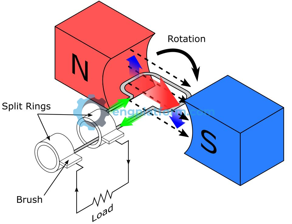
An electric generator is a machine that uses magnetism to convert mechanical energy into electric energy. Generators operate on the principle that a voltage is induced in a conductor whenever the conductor is moved through a magnetic field so as to cut lines of force
- A device called a prime mover provides the mechanical energy input, which physically turns the armature coil.
- Relative motion between the wire and the magnetic field causes a voltage to be induced between the ends of the wire.
- The generated voltage changes in magnitude as the loop cuts the magnetic lines of force at different angles.
- The generated voltage changes in polarity as the loop cuts the magnetic lines of force in two different directions.
- Two slip rings are attached to the armature wire and rotate with it.
- Carbon brushes ride against the slip rings to conduct AC current from the armature to the resistor load.
- A complete rotation of 360 degrees results in the generation of one cycle of alternating current.
Generating DC is basically the same as generating AC. The only difference is the manner in which the generated voltage is supplied to the output terminals.
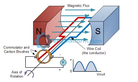
- Voltage is induced into the coil when it cuts magnetic flux lines.
- The shape of the voltage generated in the loop is still that of an AC sine wave.
- The two slip rings of the AC generator are replaced by a single split ring called a commutator.
- The commutator acts like a mechanical switch, which converts the generated AC voltage into DC voltage.
- As the armature starts to develop a negative alternation, the commutator switches the polarity of the output terminals via the brushes. This keeps all positive alternations on one terminal and all negative alternations on the other.
- The only essential difference between an AC and a DC generator is the use of slip rings on the one and a commutator on the other.
- Brushes move from one segment of the commutator to the next during the period of zero induced voltage when the coil is moving parallel to the magnetic flux, or in what is called the neutral plane.
- Any DC machine can act either as a generator or as a motor.
Motor Rotation
An electric motor operates due to the interaction of two magnetic fields. According to the well-known laws of magnetism, “like” poles (N-N or S-S) repel each other, while “unlike” poles (N-S) attract.
- The moving armature part is an electromagnet, and the fixed stator part is a permanent magnet.
- The armature starts turning when like magnetic poles repel each other.
- After rotating partway, the force of attraction between the unlike poles becomes strong enough to prevent the electromagnet from rotating.
- The rotating electromagnet continues to turn until the unlike poles are aligned. Normally, at this point, the rotor would stop due to the attraction between the unlike poles.
- Commutation refers to reversing the armature current when unlike poles of the armature and field face each other. This process reverses the polarity of the armature field.
- Like poles of the armature and field then repel each other, causing armature rotation to continue.

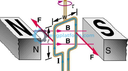
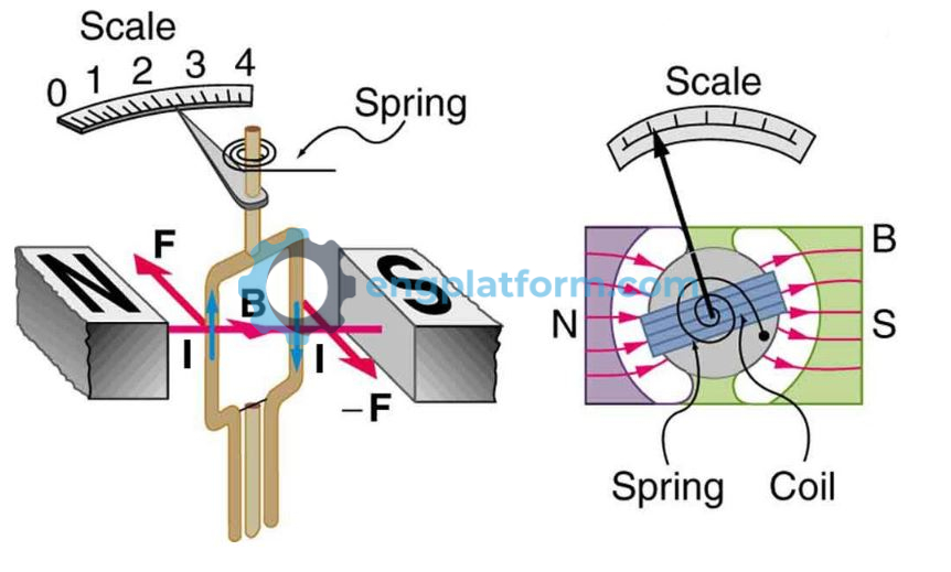
When a current-carrying conductor is placed in a magnetic field, there is an interaction between the magnetic field produced by the current and the permanent field, which leads to a force being experienced by the conductor. The magnitude of the force on the conductor will be directly proportional to the current which it carries.
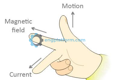
A simple method used to determine the direction of movement of a conductor carrying current in a magnetic field is the right-hand motor rule. To apply the right hand motor rule:
- The thumb and first two fingers of the right hand are arranged to be at right angles to each other.
- The forefinger is pointed in the direction of the mag-netic lines of force of the field from N pole to S pole.
- The middle finger is pointed in the direction of elec-tron current flow (− to +) in the conductor.
- The thumb will then be pointing in the direction of movement of the conductor.
- If the current through the conductor were to be reversed, the conductor would move downward.
- Note that the conductor current is at a right angle to the magnetic field. This is required to bring about motion because no force is felt by a conductor if the current and the field direction are parallel.
Rotation is the result of the interaction of the magnetic fields generated by the permanent magnets and current flow through the armature coil.
- This interaction of the two magnetic fields causes a bending of the lines of force.
- When the lines tend to straighten out, they cause the loop to undergo a rotating motion.
- The left conductor is forced downward, and the right conductor is forced upward, causing a counter-clockwise rotation of the armature.
- The magnetic fields of these conductors combine to form a resultant armature field with north and south poles that interact with those of the main stator field to exert a continuous torque on the armature.
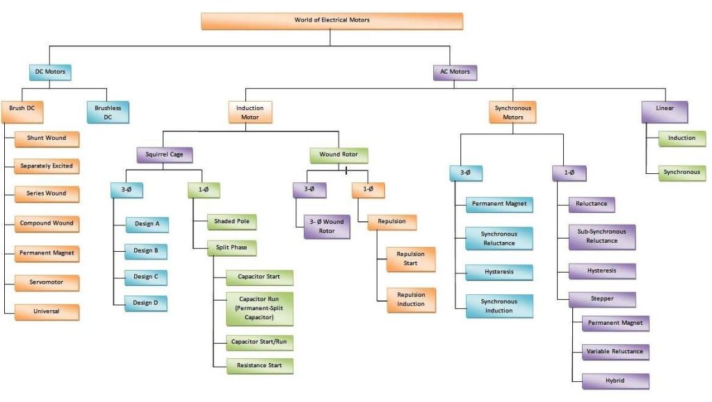
In general, motors are classified according to the type of power used (AC or DC) and the motor’s principle of operation. There are several major classifications of the motors in common use; each will specify characteristics that suit it to particular applications. Figure 5-10 shows a family tree of common types of motors.