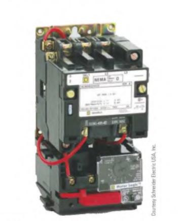
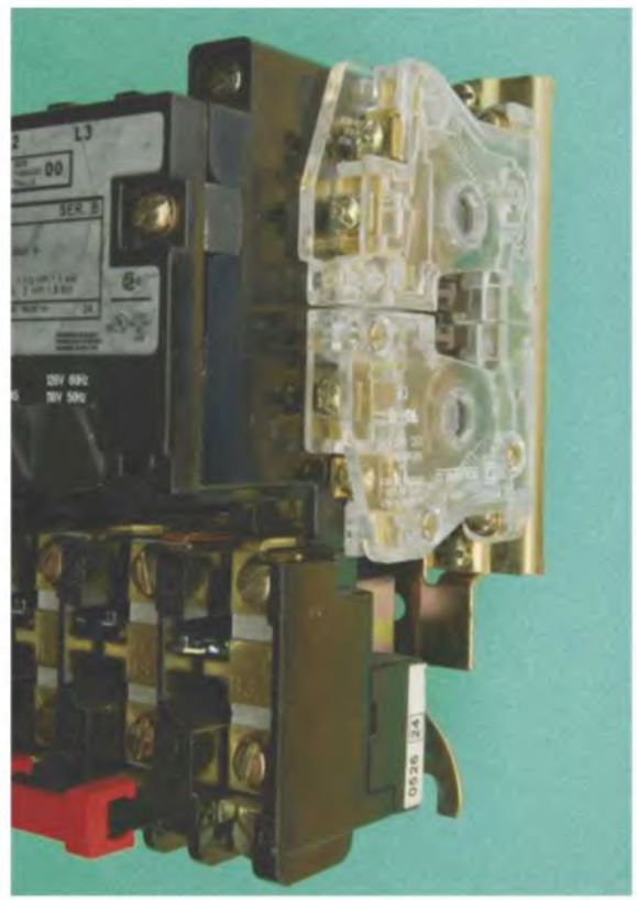
Motor starters are contactors with the addition of an overload relay. Because they are intended to control the operation of motors, motor starters are rated in horsepower. Magnetic motor starters are available in different sizes. The size starter required is determined by the horsepower and voltage of the motor it is intended to control. Two standards are used to determine the size starter needed—NEMA and IEC. The capacity of the starter is determined by the size of its load or power contacts and the wire cross sectional area that can be connected to the starter. The size of the load contacts is reduced when the voltage is doubled because the current is halved for the same power rating iP = EX T).
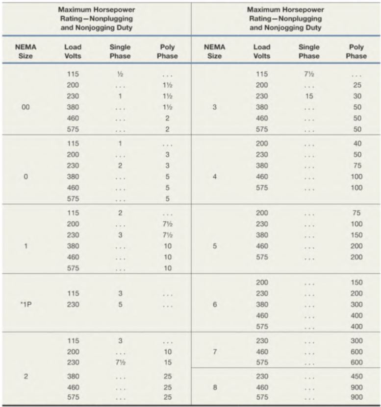
The number of poles refers to the load contacts and does not include the number of control or auxiliary contacts. Three pole starters are used to control three phase motors, and two pole starters are used for single phase motors.
NEMA and IEC
The IEC establishes standards and ratings for different types of equipment just as NEMA does. The IEC, however, is more widely used throughout Europe than in the United Slates. Many equipment manufacturers are now beginning to specify IEC standards for their products produced in the United States. The main reason is that much of the equipment produced in the United States is also marketed in Europe. Many European companies will not purchase equipment that is not designed with IEC standard equipment.
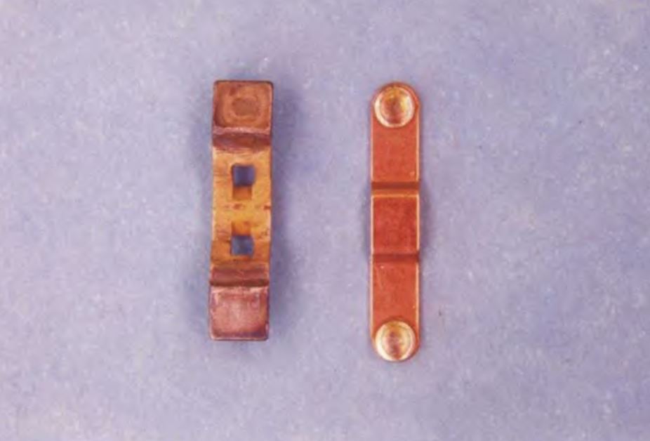
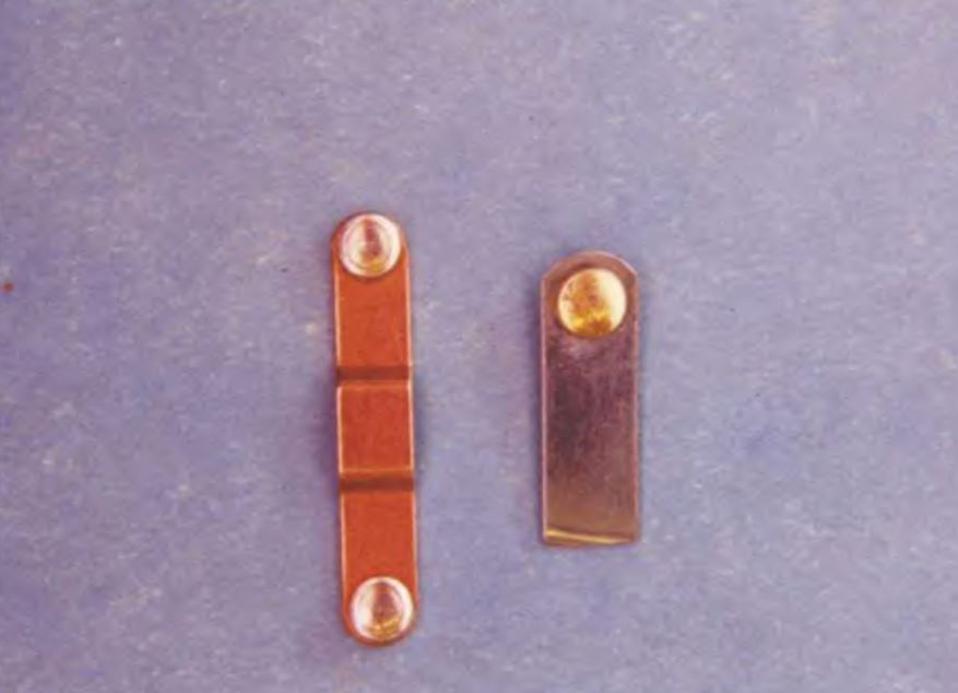
Although the IEC uses some of the same ratings as similar NEMA-rated equipment, there is often a vast difference in the physical characteristics of the two. The load contacts on the left are employed in a NEMA-rated 00 motor starter. The load contacts on the right are used in an lEC-rated 00 motor starter. Notice that the surface area of the NEMA-rated contacts is much larger than the lEC-rated contacts. This difference permits the NEMA-rated starter to control a much higher current than the TEC starter. In fact, the TEC-rated 00 starter contacts are smaller than the contacts of a small 8 pin control relay. Due to the size difference in contacts between NEMA- and lEC-rated starters, many engineers and designers of control systems specify a one to two larger size for lEC-rated equipment than would be necessary for NEMA-rated equipment.
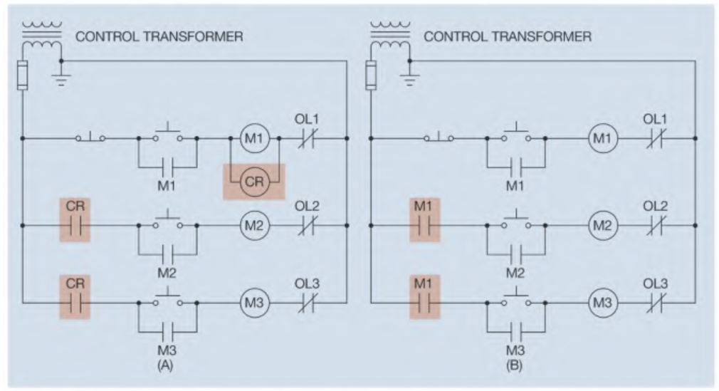
Although motor starters are basically a contactor and overload relay mounted together, most contain auxiliary contacts. Many manufacturers make auxiliary contacts that can be added to a starter or contactor. Adding auxiliary contacts can often reduce the need for control relays that perform part of the circuit logic. Motor #1 must be started before motors #2 or #3. This is accomplished by placing normally open contacts in series with starter coils M2 and M3. In the circuit shown in Figure 5-45(A), the coil of a control relay has been connected in parallel with motor starter coil Ml. In this way, control relay CR will operate in conjunction with motor starter coil MI. The two normally open CR contacts prevent motors 2 and 3 from starting until motor 1 is running. The two new auxiliary contacts can replace the two normally open CR contacts, eliminating the need for control relay CR.
CAUTION: By necessity, motor control centers have very low impedance and can produce extremely large fault currents. It is estimated that the typical MCC can deliver enough energy in an arc-fault condition to kill a person 30 feet away. For this reason, many industries now require electricians to wear full protection (flame-retardant clothing, face shield, ear plugs, and hard hat) when opening the door on a combination starter or energizing the unit. When energizing the starter, always stand to the side of the unit and not directly in front of it. In a direct short condition, it is possible for the door to be blown off or open.
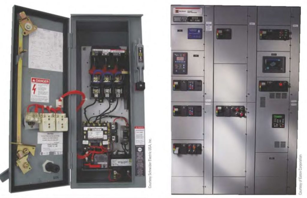
Motor starters are often grouped with other devices, such as circuit breakers, fuses, disconnects, and control transformers, and referred to as a combination starter. These components are often contained inside one enclosure.
Motor Control Centers
Motor control centers employ the use of combination starters that are mounted in special enclosures designed to plug into central buss bars that supply power for several motors. The enclosure for this type of combination starter is often referred to as a module, cubical, or can. They are designed to be inserted into a motor control center (MCC). Connection to individual modules is generally made with terminal strips located inside the module. Most manufacturers provide some means of removing the entire terminal strip without having to remove each individual wire. If a starter should fail, this permits rapid installation of a new starter. The defective starter can then be serviced at a later time.
Current Requirements
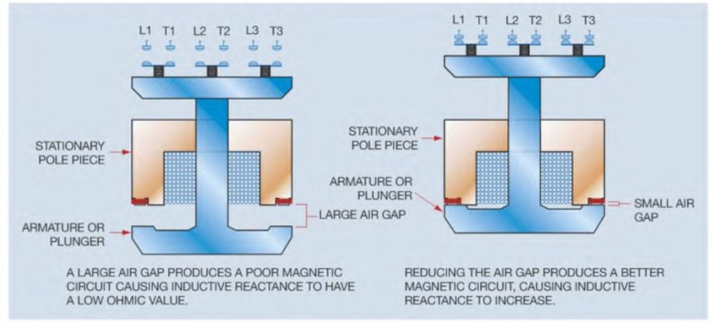
When the coil of an alternating current relay or contactor is energized, it will require more current to pull the armature in than to hold it in. The reason is thebchange of inductive reactance caused by the air gap. When the relay is turned off, a large air gap exists between the metal of the stationary pole piece and the armature. This air gap causes a poor magnetic circuit and the inductive reactance X, has a low ohmic value. Although the wire used to make the coil does have some resistance, the main current limiting factor of an inductor is inductive reactance. After the coil is energized and the armature makes contact with the stationary pole piece, there is a very small air gap between the armature and pole piece. This small air gap permits a better magnetic circuit, which increases the inductive reactance causing the current to decrease. If dirt or some other foreign matter should prevent the armature from making a seal with the stationary pole piece, the coil current will remain higher than normal, which can cause overheating and eventual coil burn out.
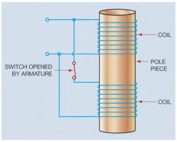
Direct current relays and contactors depend on the resistance of the wire used to construct the coil to limit current flow. For this reason, the coils of DC relays and contactors exhibit a higher resistance than coils of AC relays. Large direct current contac- tors are often equipped with two coils instead of one. When the contactor is energized, both coils are connected in parallel to produce a strong magnetic field in the pole piece. A strong field is required to provide the attraction needed to attract the armature. Once the armature has been attracted, a much weaker magnetic field can hold the armature in place. When the armature closes, a switch disconnects one of the coils reducing the current to the contactor.