Digital signals are the language of computers and other digital devices. They can be represented by two states, such as 0 and 1, or on and off.
Relays are electrical switches that can also be represented by two states, open and closed. This makes them well-suited for use in digital circuits.
Relays can be used to make logical control decisions in motor control circuits. For example, a relay could be used to turn on a motor when a certain sensor is activated. The primary programming language for programmable logic controllers (PLCs) is based on relay control logic and ladder diagrams.

Control Circuit Inputs and Outputs
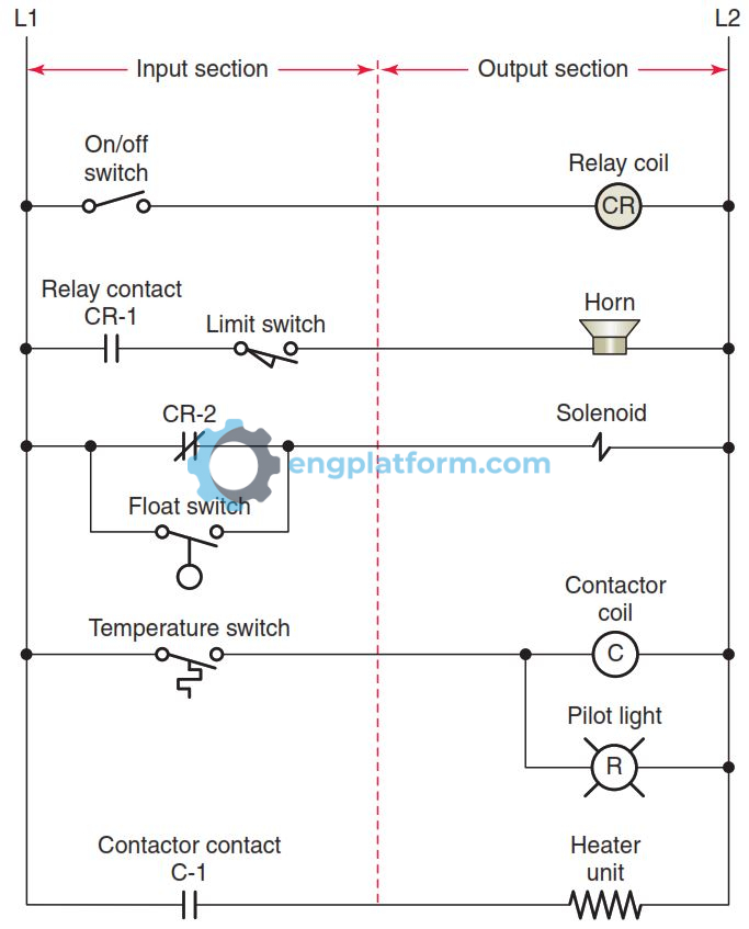
Electrical control circuits can be divided into two parts: input and output.
Input devices provide signals to the circuit. Examples of input devices include manually operated switches, push buttons, and sensors. Input signals turn on or off the flow of current in the circuit.
Output devices perform the actions desired by the circuit. Examples of output devices include contactors, motor starters, and solenoids.
Direct output devices are energized directly by the input signals. Indirect output devices are energized by the coils of relays, contactors, and starters. The contacts of these devices are the ones that actually control the load.
Motor control circuits may have one or more inputs controlling one or more outputs. A combination of input devices that either manually or automatically sense a condition and the corresponding change in condition performed by the output device make up the core of motor control. The control logic for the circuit can be summarized as follows:
- Relay coil CR is energized when the on/off switch is closed and acts to close the CR-1 contact and open the CR-2 contact.
- For the horn to energize and sound, both the CR-1 contact and the limit switch must be closed.
- The solenoid is energized and operates whenever the CR-2 contact or float switch is closed.
- When the temperature switch closes, the contactor coil energizes and acts to close the C1 contact. At the same time, the circuit is completed to the red pilot light, switching it on.
- The heater unit is energized and operates whenever contact C1 is closed.
AND Logic Function
Logic is the ability to make decisions based on different conditions. Control logic functions describe how inputs interact with each other to control outputs. These functions include AND, OR, NOT, NAND, and NOR. In electronic circuits, these functions are implemented using digital circuits called gates.
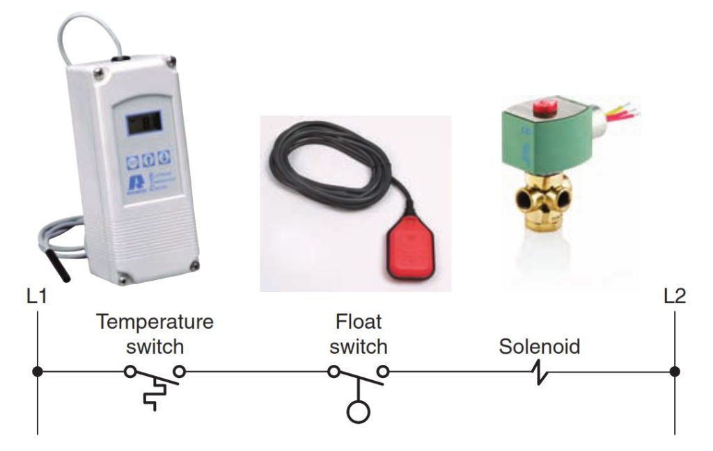
The AND logic function is like a series circuit. It means that all inputs must be closed in order for the output to be energized. This is useful for applications where the output should only be energized if all of the conditions are met.
For example, in an industrial setting, an AND logic function could be used to control a pump. The pump should only turn on if both the temperature switch and the float switch are closed. This ensures that the pump will not run if the tank is empty or if the temperature is too high.
OR Logic Function
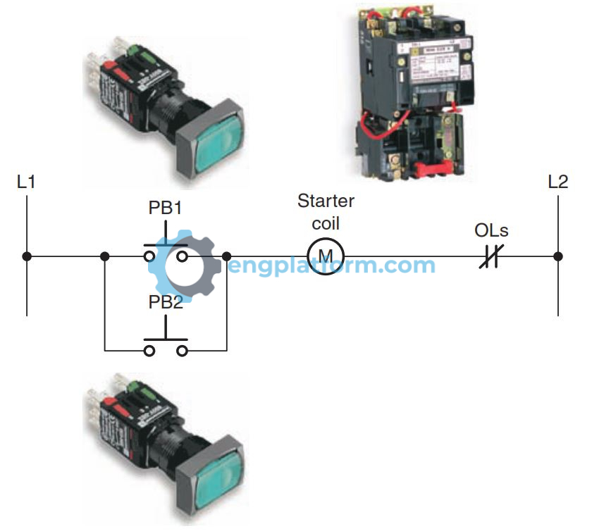
OR logic is like a parallel circuit. This means that any of the inputs can be closed in order for the output to be energized. This is useful for applications where the output should be energized if any of the conditions are met.
For example, in an industrial setting, an OR logic function could be used to control a light. The light should turn on if either the pushbutton in the office or the pushbutton in the warehouse is pressed. This ensures that the light can be turned on from either location.
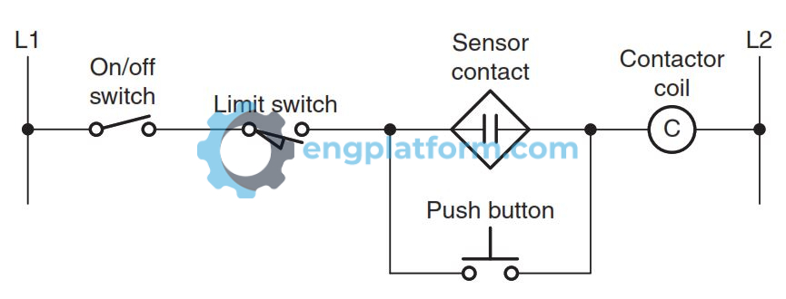
Combination Logic Functions
Control circuits often require more than one type of logic function when more complex decisions need to be made. In this control application, the output is a contactor coil that is controlled by combined AND/OR logic functions. Both the on/off switch and limit switch in addition to the sensor contact or push button must be closed to energize the contactor coil.
NOT Logic Function
NOT logic is different from AND and OR logic because it uses a single normally closed input device instead of a normally open one. This means that the output of a NOT logic function is energized when the input is not energized.
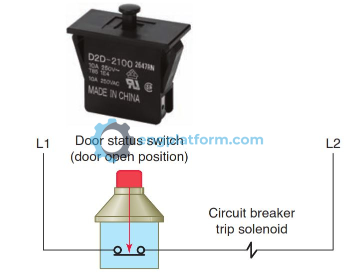
A common example of NOT logic is a safety switch. A safety switch is normally closed, meaning that the contacts are touching and the circuit is complete. When the safety switch is opened, the contacts separate and the circuit is broken. This de-energizes the output load, which is typically a machine or other device.
Safety switches are used to prevent accidents. For example, a safety switch might be used to stop a machine if a door is opened. This prevents the operator from being injured by the machine while it is running.
NAND Logic Function
NAND logic is a combination of AND and NOT logic. It uses two or more normally closed contacts connected in parallel to control the load.
In the example you provided, two float switches are connected in parallel using NAND logic to control a pump motor. Both float switches must be open for the pump motor to shut off automatically. This means that the pump motor will continue to run as long as either or both tanks are below the full level.
This circuit is useful for ensuring that the pump motor does not run dry. If either tank is empty, the pump motor will continue to run until the tank is full. This prevents the pump motor from overheating and failing.

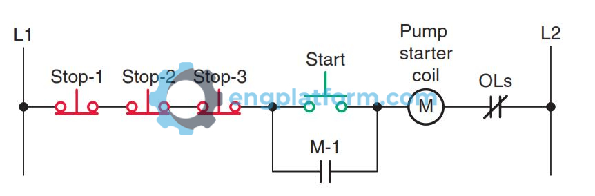
NOR Logic Function
NOR logic is a combination of OR and NOT logic. It uses two or more normally closed contacts connected in series to control the load.
In the example you provided, three stop push buttons are connected in series using NOR logic to control a motor. If any one of the three stop push buttons is pressed, the motor will stop. This means that the motor can be stopped from three different locations.
This circuit is useful for applications where the motor needs to be stopped quickly, such as in an emergency. It is also useful for applications where the motor needs to be stopped from multiple locations.