Operation
Solid-state relays (SSRs) are electronic switches that use semiconductors to control the flow of electricity. They have no moving parts, unlike electromechanical relays (EMRs). SSRs have an input side that receives a voltage signal from the control circuit and an output side that switches the load. The input side and the output side are electrically isolated from each other.
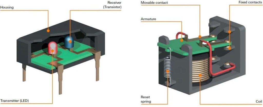
A common way to isolate the input and output sides is to use an optocoupler. An optocoupler is a device that uses light to transmit a signal from one circuit to another. The input side of the SSR illuminates an LED, which activates a photodetector on the output side. The photodetector then triggers the output side, actuating the load.
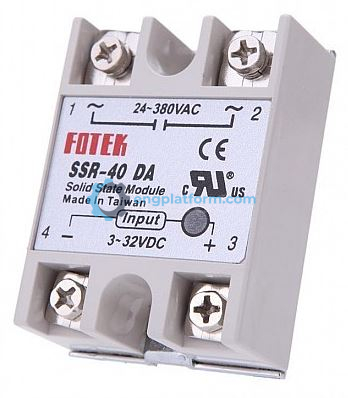
SSRs come in a variety of configurations, including “hockey-puck” and “ice-cube” types. On schematics, SSRs are typically represented by a square or rectangle. The internal circuitry is not shown, and only the input and output connections are given.
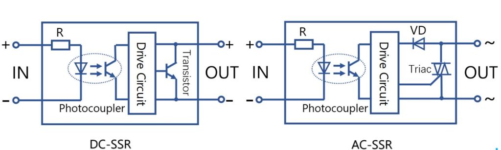
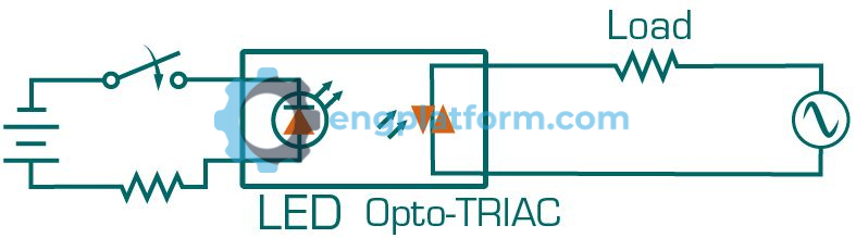
Solid-state relays are constructed with different main switching devices depending on the type of load being switched. If the relay is designed to control an AC load, a triac is commonly used as the main switching semiconductor. The operation of the circuit can be summarized as follows:
- A current flow is established through the LED connected to the input when conditions call for the relay to be actuated.
- The LED conducts and shines light on the phototransistor.
- The phototransistor conducts switching on the triac and AC power to the load.
- The output is isolated from the input by the simple LED and phototransistor arrangement.
- Since a light beam is used as the control medium, no voltage spikes or electrical noise produced on the load side of the relay can be transmitted to the control side of the relay.
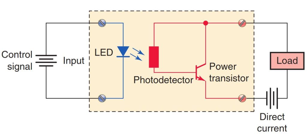
Solid-state relays intended for use with DC loads have a power transistor rather than a triac connected to the load circuit. The operation of the circuit can be summarized as follows:
- When the input voltage turns the LED on, the photodetector connected to the base of the transistor turns the transistor on, allowing current flow to the load.
- The LED section of the relay acts like the coil of the electromechanical relay and requires a DC voltage for its operation.
- The transistor section of the optocoupler inside the SSR is equivalent to the contacts in a relay.
- Because solid-state relays have no moving parts, their switching response time is many times faster than that of electromechanical relays. For this rea-son, when loads are to be switched continually and quickly, the SSR is the relay of choice.
Specifications
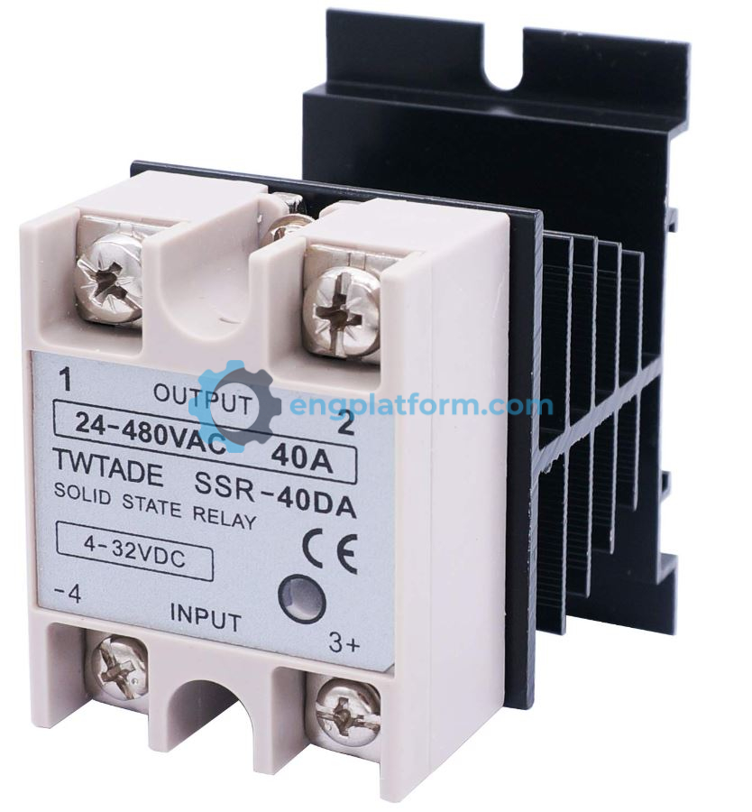
Applying a specified amount of pickup voltage activates the input control circuit of a solid-state relay (SSR). SSRs typically have a variable input voltage range, such as 5 V DC to 24 V DC, making them compatible with various electronic input devices. The output voltage ratings of SSRs range from 5 V DC up to 480 V AC. Although most SSRs are designed for a rated output current of under 10 A, relays mounted on heat sinks can control up to 40 A.
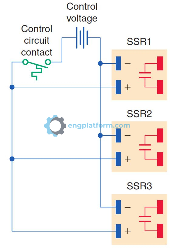
The majority of SSRs are single-pole devices, as multipole relays pose a greater power dissipation problem. When multiple poles are required, a multipole solid-state module can be used. Alternatively, several SSR control circuits can be wired in parallel to provide the equivalent function of a multipole electromagnetic relay. For instance, in this application, three single-pole solid-state relays are used to switch current to a three-phase load. The input section may receive signals from various sources such as device contacts or sensor signals. When the control circuit contact closes, all three relays actuate to complete the current path to the load.
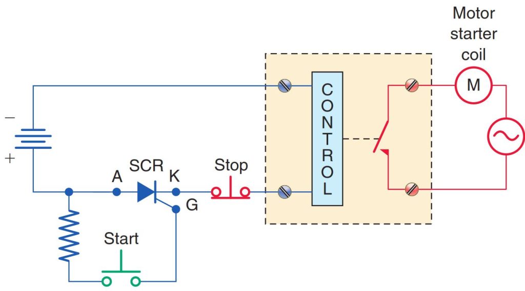
The standard single-pole SSR configuration works fine with two-wire control; however, when it becomes necessary for it to be used in a three-wire control scheme, the problem of the holding circuit arises. An additional relay can be wired in parallel to the SSR to act as the holding contact. Another solution is to use a DC control circuit with a silicon-controlled rectifier (SCR) for latching the load. The operation of the circuit can be summarized as follows:
- The SCR will not allow current flow from anode (A) to cathode (K) until current is applied to the gate (G).
- When the start push button is pressed, current flows through the gate, which triggers the anode-to-cathode section of the SCR and relay control circuit into conduction.
- The SCR remains latched on after the start push button is released, and the circuit must be opened to stop the anode-to-cathode current flow. This is accomplished by pressing the stop push button.
Switching Methods
SSRs operate with several different switching methods. The type of load is an important factor in the selection of the switching method.
- Solid-state relays (SSRs) can use different switching methods, depending on the type of load.
- Zero-switching relays turn on the load when the control voltage is applied and the voltage at the load is zero. They turn off the load when the control voltage is removed and the current in the load is zero. This is best for resistive loads, such as lamp filaments, because it reduces wear and tear from high-voltage transients.
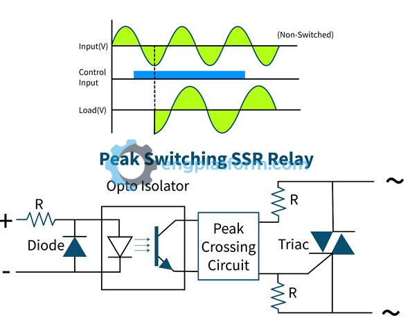
- Peak-switching relays turn on the load when the control voltage is present and the voltage at the load is at its peak. They turn off the load when the control voltage is removed and the current in the load is zero. This is best for inductive or capacitive loads, where the voltage and current are approximately 90 degrees out of phase.
- Instant-on relays turn on the load immediately when the control voltage is applied and turn it off immediately when the control voltage is removed. This is best for loads that are a combination of resistance and reactance, where the voltage and current phase angle varies.
Solid-state relays have several advantages over electromechanical types:
- The SSR is more reliable and has a longer life because it has no moving parts.
- It is compatible with transistor and IC circuitry and does not generate as much electromagnetic interference.
- The SSR is more resistant to shock and vibration, has a much faster response time, and does not exhibit contact bounce.
Solid-state relays (SSRs) are more susceptible to damage from voltage and current spikes than electromechanical relays (EMRs). Other issues with SSRs include:
- Thermal dissipation: SSRs generate heat, which is a result of the power loss due to the operating voltage drop created across the switching semiconductor. SSRs controlling loads rated at more than 5 amps require a heat sink for reliable operation. The size and thermal rating of the heat sink increases as the load current carried by the SSR increases, or as the operational ambient temperature increases.
- Leakage current: SSRs in the blocked or output off state do not have an infinite impedance across their terminals. As a result, a small amount of current, called leakage current, flows through the load in the off state. Although the leakage current is normally less than 1 mA, it may present a problem in applications controlling very low loads (small solenoid valves, etc.) because this current may be sufficient to keep the load energized even after the relay is switched off.
- Higher cost: SSRs are more expensive than comparable EMRs. This is because SSRs use semiconductors, which are more expensive than the components used in EMRs. If multiple loads need to be switched, the cost disadvantage of SSRs can become more pronounced.