Wiring Diagrams
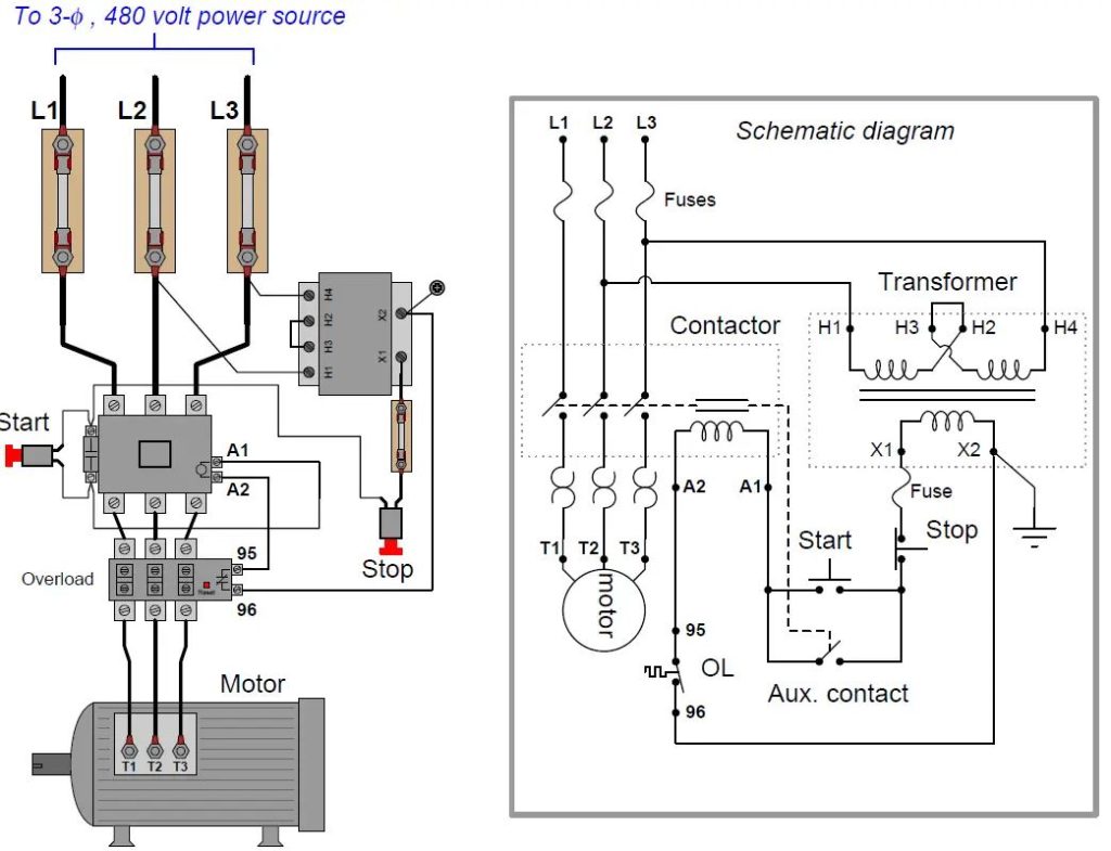
Wiring diagrams are a visual representation of the point-to-point wiring between components of an electric system and their physical relation to each other. They may include wire identification numbers assigned to conductors in the ladder diagram and/or color coding. Coils, contacts, motors, and the like are shown in the actual position that would be found on an installation. These diagrams are helpful in wiring up systems, because connections can be made exactly as they are shown on the diagram. A wiring diagram gives the necessary information for actually wiring up a device or group of devices or for physically tracing wires in troubleshooting. However, it is difficult to determine circuit operation from this type of drawing.
The paragraph describes the routing of wires in cables and conduits. A conduit layout diagram is a visual representation that shows the start and end points of electrical conduits and the approximate path taken by each conduit from one point to another. The diagram is often integrated with a drawing that includes the conduit and cable schedule. The schedule provides a tabulated list of each conduit, including its number, size, function, and service. It also includes the number and size of wires that are to be run in each conduit.
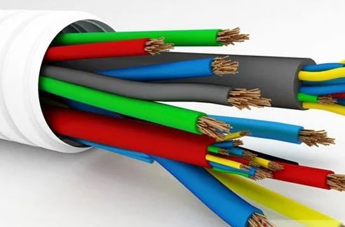
Wiring diagrams show the details of actual connections. Rarely do they attempt to show complete details of panel board or equipment wiring. Wires encased in conduit C1 are part of the power circuit and sized for the current requirement of the motor. Wires encased in conduit C2 are part of the lower-voltage control circuit and sized to the current requirements of the control transformer.
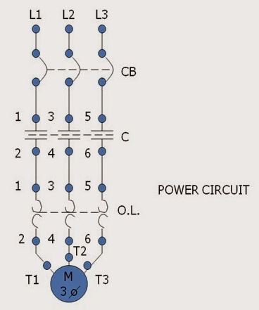
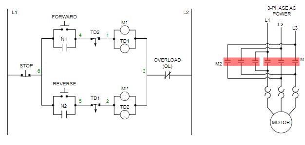
Wiring diagrams are frequently used in tandem with ladder diagrams to simplify the comprehension of the control process. The wiring diagram displays both the power and control circuits. A separate ladder diagram of the control circuit is included to provide a clearer understanding of its operation. By following the ladder diagram, it can be observed that the pilot light is connected in such a way that it will be illuminated whenever the starter is energized. The power circuit has been excluded for clarity, as it can be easily traced on the wiring diagram (heavy black lines).
Single-Line Diagrams
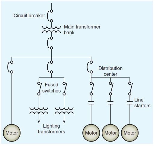
The paragraph explains that a single-line diagram is a schematic representation of an electric circuit that uses symbols and a single line to depict all the major components. Some manufacturers of motor control equipment use a single-line drawing as a guide in studying motor control installations. The diagram simplifies the installation to its most basic form, while still showing the necessary requirements and equipment in the circuit.
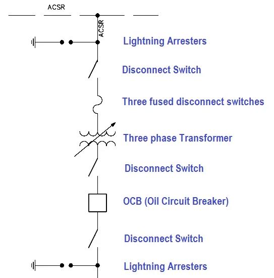
The paragraph explains that power systems are complex electrical networks that can be spread over large areas. They are mostly three-phase networks, meaning each power circuit comprises three conductors and all devices such as generators, transformers, breakers, and disconnects installed in all three phases. These systems are so intricate that a conventional diagram showing all the connections is impractical. In such cases, a single-line diagram is used to communicate the basic arrangement of the power system’s components in a concise manner. These diagrams are also known as “power riser” diagrams.
Block Diagrams
A block diagram is a schematic representation of complex electrical/electronic systems that uses blocks to represent the major functional parts of the system. Unlike circuit diagrams, individual components and wires are not shown. Instead, each block represents electrical circuits that perform specific functions in the system. The functions the circuits perform are written in each block. Arrows connecting the blocks indicate the general direction of current paths.
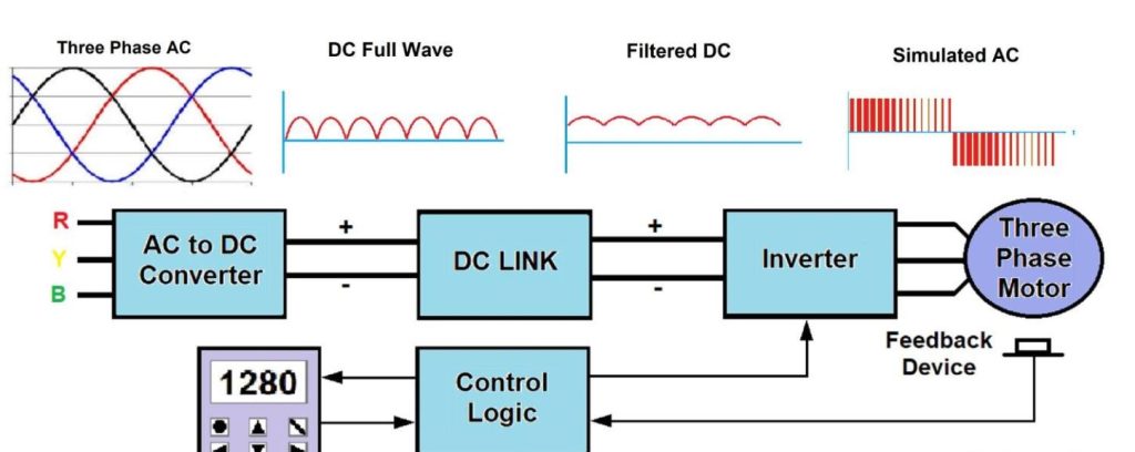
A variable-frequency drive (VFD) is an electronic device that controls the speed of an AC motor by varying the frequency supplied to the motor. The VFD also regulates the output voltage in proportion to the output frequency to provide a relatively constant ratio (volts per hertz; V/Hz) of voltage to frequency, as required by the characteristics of the AC motor to produce adequate torque. The VFD is made up of two main blocks: rectifier and inverter.
The rectifier block is a circuit that converts or rectifies its three-phase AC voltage into a DC voltage. It receives 60 Hz three-phase power as input.
The inverter block is a circuit that inverts, or converts, its DC input voltage back into an AC voltage. The inverter is made up of electronic switches, which switch the DC voltage on and off to produce a controllable AC power output at the desired frequency and voltage.