What Is Arduino?
The term Arduino is used to describe both the physical Arduino board (of which the most popular type is the Arduino Uno) and the Arduino system as a whole. The system also includes the Arduino IDE software you need to run on your computer (to program the board) and the peripheral shields that you can plug into an Arduino board. Arduino has also come to mean a whole array of third-party Arduino compatible boards that have nothing to do with the Arduino organization, but that will work with the Arduino IDE. To use an Arduino, you also need a “proper” computer. This can be a Mac, Windows PC, Linux PC, or even something as humble as a Raspberry Pi. The main reason that you need the computer is so you can install programs onto the Arduino board. Once installed on the Arduino, these programs can then run independently. The Arduino can also communicate with your computer over USB. While the computer is connected, you can send messages in both directions.

An Arduino is unlike a conventional computer in that it has hardly any memory, no operating system, and no keyboard mouse or screen interface. Its purpose is to control things by interfacing with sensors and actuators. So, for instance, you might attach a sensor to measure the temperature and a relay to control the power to a heater.

Here is a short selection of some of the amazing projects that have been built using an Arduino:
• Bubblino—an Arduino linked to a bubble machine that blows bubbles when you tweet it!
• 3D LED cubes
• Geiger counters
• Musical instruments
• Remote sensors
• Robots
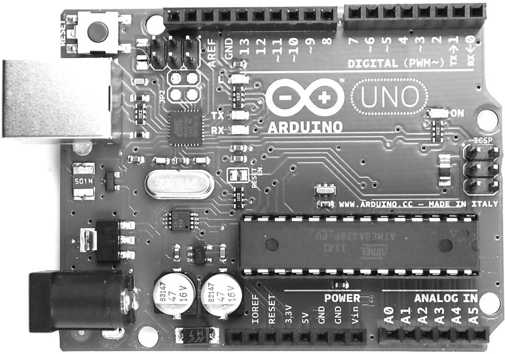
A Tour of Arduino
Starting at the top, next to the USB socket in the top-left corner, is the Reset switch. Clicking this sends a logic pulse to the microcontroller’s Reset pin, clearing the microcontroller’s memory so it can start its program fresh. Note that any program stored on the device is retained because it is kept in nonvolatile flash memory—that is, memory that remembers even when the device is not powered on.

Power Supply
The Arduino can either be powered through either the USB connection or the DC power socket below it. When powering the Arduino from a DC adaptor or batteries, anything between 7.5 and 12V DC can be supplied through the power socket. The Arduino itself only uses about 50 mA. So a small PP3 9V battery (200 mAh) will power it for around 4 hours. When the Arduino is powered on, the power LED on the right of the Uno (on the left of the Leonardo) is lit.
Power Connections
Apart from the first connection, you can read the connection names next to the connectors. The first unlabeled connection is reserved for later use. The next pin, IOREF, indicates the voltage at which the Arduino operates. Both the Uno and Leonardo operate at 5V, so this pin will always be set at 5V, but you will not use it for anything described in this book. Its purpose is to allow shields attached to 3V Arduinos like the Arduino Due or m0 to detect the voltage at which the Arduino operates. The next connect is Reset. This connection does the same thing as pressing the Reset switch on the Arduino. Rather like rebooting a PC, it resets the microcontroller to begin its program from the start. The Reset connector allows you to reset the microcontroller by momentarily setting this pin low (connecting it to GND). It is fairly unlikely that you’ll need to do this, but it’s quite nice to know that the connector is there. The remaining pins provide different voltages (3.3, 5, GND, and Vin), as labeled. GND, or ground, just means zero volts. It is the reference voltage to which all other voltages on the board are relative. Vin is the input voltage supplied by the DC power jack (if it is used). The two GND connections are identical; having more than one GND pin to connect things to is useful. In fact, there is another GND socket at the top of the board.
Analog Inputs
The next section of connections is labeled Analog In 0 to 5. These six pins can be used to measure the voltage connected to them (5V maximum) so the value can be used in a sketch. Although labeled as analog inputs, these connections can also be used as digital inputs or outputs. By default, however, they are analog inputs.
Digital Connections
Now let’s switch to the top connector, starting on the right side. We have pins labeled Digital 0 to 13. These can be used as either inputs or outputs and are therefore called GPIOs (general purpose input outputs). When using them as outputs, you can control them from a sketch. If you turn them on from your sketch, they will be at 5V, and if you turn them off, they will be at 0V. As with the supply connectors, you have to be careful not to exceed their maximum current capabilities. These connections can supply 40 mA at 5V—more than enough power to light a standard LED, but not enough to drive an electric motor directly. Note that the total current used by all pins must not exceed 200mA.